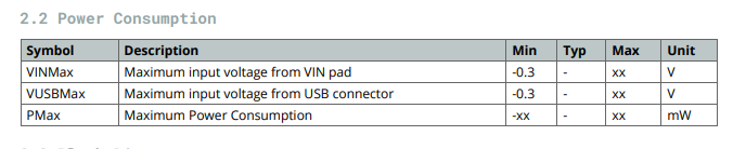
When I consulted the datasheet to see power consumption data for the Portenta H7 I was met with this beauty:
Is there an updated datasheet that actually has this information?
When I consulted the datasheet to see power consumption data for the Portenta H7 I was met with this beauty:
Is there an updated datasheet that actually has this information?
Did you check...
https://docs.arduino.cc/static/2805c158433f99d5997c7f736645fbb4/ABX00042-ABX00045-ABX00046-datasheet.pdf
EDIT... sorry I was trying to link this from the datasheet... MC34PF1550A0EP Product Information|NXP
Yes, that gives me the upper limit of what the onboard power supply can provide, but not the nominal power consumption of the Portenta board.
Edit: To be fair, the table I pasted in the first post was for Pmax, which would align with the max output of the PSU, so your response does answer that question. Now I wonder what I can expect for nominal power consumption...
If I ever need what to know what it actually uses ... trust your measurements (multimeter?) rather than a datasheet.
It really depends how much accelerator you use to calculate the fuel consumption. ![]()
Yup, I agree. Thanks for the help.
@avi-brown
can you share with us how much power used by portenta h7?(measured by any device like multimeter or...)
Hi @yari0757, I haven't had a chance to measure this experimentally yet, but if you'd like to share with me a test script I'm happy to include it in my tests and post the results here when I have a chance.
All the best.
Interesting question: I am curious and did measurement:
4.99V on VIN and 282 mA = approx. 1.5W power consumption
Conditions:
SDRAM enabled, SD card enabled, ETH enabled, USB-C for UART (plus SPI device)
Not used/no enabled:
WiFi/BT and crypto chip (WiFi could contribute much more...)
So, I would assume:
regular use case: 5V and 300 mA, as peak maybe 400 mA = 2W power consumption (as max., fine for USB and USB-C)
Remarks:
I did the measurement by using VIN (provide power there).
VIN has a Schottky Diode, so VBUS_USBC is combined with VIN:
VBUS_USBC is 5.05V (from PC) and VIN after diode: 4.76V (Schottky diode: -0.3V drop)
I provide power on VIN (as 5.00V, "override" the diode): with USB-C connected: my VIN current is a bit lower with USB-C connected (obvious: part comes now also via USB-C, not just VIN).
And: my measurements are with PMIC configured for 3V3 (not just 3V1 = default). So, a bit higher current on my side (I have tweaked PMIC chip config).
At the end:
Looks pretty good: and based on my temperature measurements: it looks like the board can handle heat dissipation even with 2W power consumption and its small footprint.
So, assume: 2W power consumption (and you should be at the save side).
Hi,
I have a side question, still concerning power or more precisely voltage input. I tried powering my Portenta via the Vin pin with a 5V regulated power supply (5V 600mA) and when I do that the portenta works fine except for the 5V pin that only goes to about 1.2V, regardless of what is connected to it.
If I understand correctly the schematics, the 5V pin is directly connected to the USB power supply which is in turn connected to the Vin pin via a Schottky diode. And the Vin pin is the one directly connected to the PSU.
So to get 5V on the 5V pin one must either power the board via USB or use this pin (5V) as the power input.
On a side note, the PSU seems to tolerate up to 24V for supply (VBusIn) so applying this much to Vin shouldn't damage the board.
Isn't it correct, when you power via VIN and USB-C is not connected the +5V pin does not have a voltage?
Sure, PMIC might tolerate up to 24V - but I would not do it:
the higher the input voltage the more must be "killed" (there are 3 LDOs inside). The chip will get really hot. And this chip is already the hottest on board. So, higher voltage as input can result in an overheat and PMIC gets damaged (or: it shuts down all).
Yes, it is correct, there is no voltage on the +5V pin when the board is powered via the Vin pin. You are right, there might be some issues with powering the board with 24V but I just wanted to share the info so that other people know that the Vin pin is pretty tolerant.
thank you. it is very helpful.
can i ask you measure the power used when portenta h7 go to sleep mode? maybe by using delay() function(some where i red mbed OS handle sleep mode when using delay function).
I don't find any deep sleep mode function for it. if you know any function please tell me.
thanks again
Deep sleep on Portenta, some hints based on my understanding how to do (and measure):
Use a scope to measure power consumption:
Current drawn by MCU can be very dynamic. With an ampere meter you get just the "average".
Using a scope, with a shunt resistor (e.g. 1 Ohm) and measure - better "display" the voltage drop over it - makes it better to see the dynamic behavior.
Deep Sleep mode is "Frequency-Voltage-Scaling":
Just to put the MCU into a "sleep" mode is not enough: there is not really a "sleep mode", except to stop the MCU to continue with code execution, e.g. instruction WFI (Wait For Interrupt).
It needs active code:
at least, before entering "sleep mode" (before doing WFI), you lower the core clock frequency. This needs an action to re-program the SystemClock.
I have seen in Arduino code that they provide clock config with parameter, e.g. "slowSpeed".
In addition, when you lower the clock, you could (should) also lower the core voltage. Now the core with slower clock does not need anymore 3.3V (or 3.1V), you can lower it.
But doing so: you have to go to PMIC and select a different profile: the PMIC chip has three different profiles to select its related voltage (high voltage = high performance, medium voltage = reduces performance and "sleep mode" = lowest voltage provided to MCU).
This can be selected, I think, pretty easily with a simple command on PMIC or to trigger an external signal:
I think, there is a GPIO signal from MCU to PMIC to do so.
So, for a real sleep mode, it needs this:
The ratio how much you can lower voltage with frequency is "Frequency-Voltage-Scaling". I think there is a bit of info in datasheet about this correlation.
And additional remark (for a complete system): if you lower voltage, clocks and stop MCU ... think about what happens with external SDRAM: it is not refreshed anymore, it can lose content.
So, often in such dynamically powered systems you might need to save data before going to sleep and to restore the data.
As I saw in datasheet, you can also bring internal SRAM in MCU to "retention mode": you can lower the voltage, bring a domain to "sleep mode", the RAMs will retain the content but this domain is not access-able without doing something (e.g. getting the wake-up call/INT).
So, you can play also with MCU internal domains, to bring them into retention mode, to lower the current drawn. Even your code keeps going to run code in one domain, such another domain is not usable anymore (unless you change the domain mode again before using it again).
Real deep sleep (or low power mode) is a very complex issue. It needs for sure a system design and code support to do so. Just to say "now enter sleep mode" is not a single instruction.
So, you have options to play with:
I cannot imagine that such a complex power changing mode is really implemented in Arduino code. I saw some hooks already there to support (e.g. SystemClock called for low speed).
A real effective "Sleep Mode" on MCUs (even they support) is the most complex topic.
Besides "data retention" (e.g. SDRAM, internal Domains) - think also about peripheral devices (e.g. SPI, I2C, UART drivers):
They can lose their state, Potentially, you had to reconfigure devices after coming back from "sleep mode" so that they start working again (in correct state).
Also: you have to implement so much logic, e.g. "when could sleep mode be entered?". As long as there is still something going on, e.g. on SPI, I2C, even ETH (network) - you cannot power down. Do you queue the power down event? And you have to make a "tradeoff": how long to wait until all is calm in system (no other devices needed anymore, not doing data transfer, e.g. UART is 'quiet').
And when you decide to enter now sleep mode - what to do when during this sequence a new request comes in, e.g. a new UART character, a wake up again? How to interrupt and roll-back?
Very complex topic.
The easiest way seems to me is:
I could imagine: lowering the SystemClock will show you a decrease in current consumption. But the biggest contribution (even lower current drawn) comes from lowering the core voltages (in slow clock condition).
Any mistake, e.g. accessing a domain not back from retention mode, forgotten to enable again, makes debugging very hard.
A debugger can also force the system (MCU) to power on, accessing via debugger in "low power mode" to enable all again. So, a HW-debugger might not help to investigate the system behavior.
Sleep Mode is a complex system design (with deep knowledge about datasheet for MCU and understanding the entire system, the SW structure and what is going on, dynamically).
And measuring the effectiveness needs a scope, the dynamic measurement of current drawn (esp. if your system would wake up again within few seconds/milli-seconds again).
BTW: delay() for my understanding is not related to power modes. It just puts your current thread (task) into pending state.
Other threads are still running, just this thread is waiting for an event (e.g. time expired).
I use delay() just in combination with RTOS, with threads (tasks): "now, nothing to do anymore here - give other threads a chance to run".
Nothing else: not related to any power reduction. Even no thread would be in active state, all are waiting for something: your MCU runs still in full speed in the RTOS scheduler (waiting to see another event to "wake up" a thread again). Nothing saved on power.
your are great! thank you
