As the title of the topic says, I want (need) to use a 24V~ transformer. The system has 5 relays and 2 x Atmega328. I'm using the AD converter to reed some temperatures (with NTC) so the linearity of the supply is really important; as I calculated, it needs less then 750mA.
Could someone help me with this issue?
Thank you in advance!
Regards,
Marius
PS If the person who wants to help me needs more info, just ask!
I opted for relays with 5V coil, to avoid different voltage values.
The transformer is 220V-24V.
The transformer already exists in the electrical panel and is used to supply some servomotors and some contactor coils.
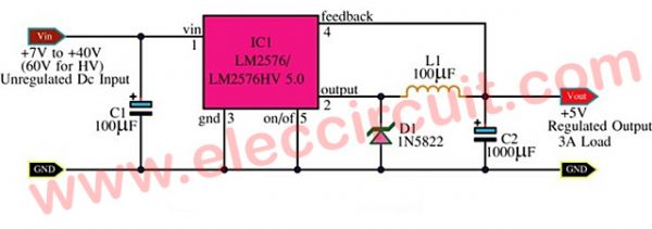
Anyone knows if the LM2576 is a good solution? I want to avoid the problems with the noise the AD converter to have a clear read of the temperature.
I need to mention that the application is for the industry environment, so a really nosy environment. It needs to be very reliable too!
Thank you!
Rather than building your own, a recent google query resulted in finding that dc to dc stepdown switching regulators are available at a very modest price. A few more components such as a full wave bridge rectifier and a couple of capacitors oughta get the 24vac from your transformer into a dc that can be fed to the regulator. Then the regulator could provide power to the arduino, relays, and other 5vdc components. Looks like you've got all that figured out. - Scotty
If you use decoupling capacitors properly and use one of those regulated dc supplies you should be fine
I've bought one that was 12-24v -> 5v 3amp and it worked well, I even had a 1F 5.5v supercap for those short high current pulls, but this was for like 2 amps not 750ma and it worked perfect, and looked very clean on the oscilloscope
I still have this problem! Looks like is turning in a BIG one!
I've used the TS2576 and it didn't work long time (about 15 min)! Very hot -> BUF -> smoke -> quiet!
And another thing: to the same transformer I connected a servo (24V~) and when I disconnect it, the chip freezes! I've measured the voltage from the Vin of the TS2576 and I had 37V.
Could anyone, PLEASE!!! help me to solve this problem?
Checked it all? you sure all values of components are correct including the inductor ?
This is supposed to be only a partial schematic am i right ?!? What about the rest ?!?
Before Vin I have a 24V~ transformer, then a rectifier bridge (2A, 80V).
After... 2xAtmega328, 1xLCD... nothing relevant to the problem. All I have "after" works perfect with my homemade power supply.
I verified the voltage after the rectifier bridge and the filter (capacitor) and I had 37V.
Did u check the voltage with a mulimeter coming out of the transformer? An unload3d transformer has a higher voltage output and assuming a 24v ac you'll get 33v dc and when 37 volts dc comes from 26 volts ac and that seems to be your problem
the peak voltage of 60hz ac is 1.41(square root of two) the rms, the rectifier and cap keeps it at its highest voltage
Well, seems to be a big problem...As you cant solve it.
Not sure what to say, as the schematic is quite a well tested one. So only option here is some error on your part( solder, values of the caps ?!? Only you can answer that) or a defective component. You sure about the inductor value ?!? Correftct pinage?! Have a llook at this PCB to make sure you have the pins matching yours...Dont know what to say, tbh