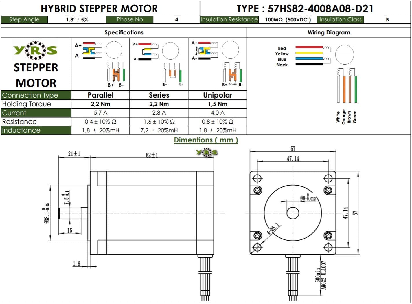
I was using six NEMA 23 stepper motors and six TB6600 analog drivers, which can operate with 9–42 V DC. The motors were powered by an external power supply that provides 12 Volts at 18 Amps. I had an original MEGA 2560 R3 board. Initially, for testing, I connected only a single driver to the Arduino using analog pins. I calculated my angle values in MATLAB, converted them to steps, and sent the data via a USB cable. My Arduino was constantly powered by a 12 V adapter, and the USB connection remained plugged in (to receive data from my computer).
After achieving good results with a single motor, I connected all of them to the board. Initially, the motors moved a little, but then everything stopped with a knocking sound. I disconnected everything and connected only the Arduino to my computer via USB. However, the computer no longer recognized the Arduino on any COM port—most likely, the USB interface is damaged. I read in some articles that burning the bootloader might help, but as a novice, I don’t have the required tools or experience.
I came up with the idea of using three MEGA boards (each controlling two stepper motors) to possibly solve this issue. I will still send the step values using USB, but this time I won’t power the boards with a 12 V adapter connected to a wall outlet. Instead, they will draw power only from the USB ports of a laptop. In this configuration, each clone board will use four analog pins (for two step and two direction signals) and one ground.
Is my approach correct? Will there be any issues?
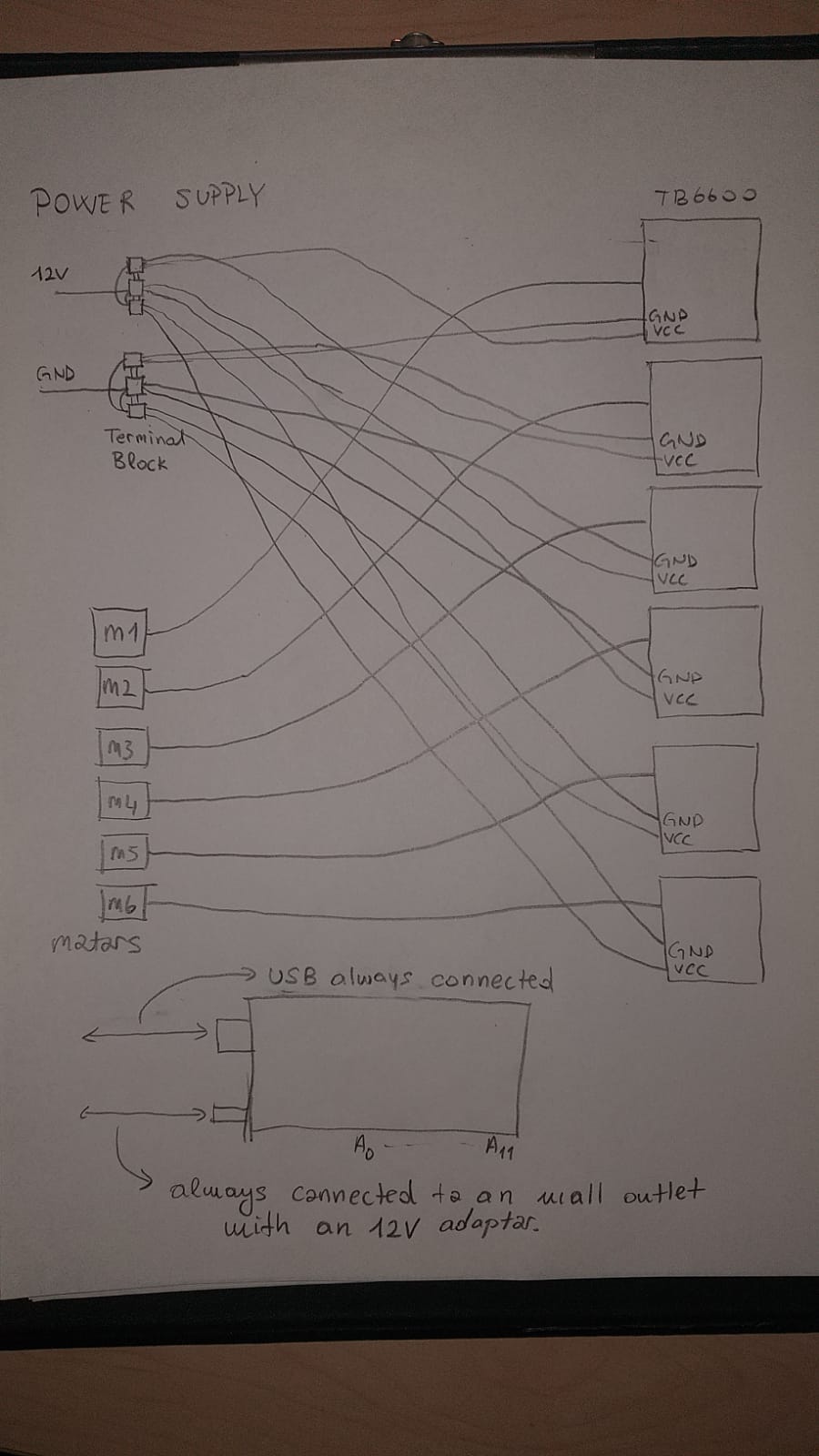
The image below shows the wiring for a single driver–motor–board setup. It matches my exact wiring. I can give you more information if I have missed any.
I will be powering the stepper motors with my external power supply (12V-18A), external power supplies 12 V and GND cables will go directly to TB6600 VCC and GND.
In principal, nothing you described would have damaged your mega. You did not unknowingly exceed some limit, as far as I can tell.
The motor driver board will place only a tiny load on the mega's pins. Connecting 3 drivers should not be a problem at all.
So in practice I imagine something else you did accidentally, maybe just for a moment, caused the damage. We will probably never know.
The "burning bootloaders" idea sounds like desperately clutching at straws. Damage caused by accidentally connecting something incorrectly is extremely unlikely to have the only effect of scrambling the flash memory of a chip.
Using 3 mega will not help. In fact it will make things more difficult and less likely to succeed and increase the danger of another random accident.
It was working very good when I connected only a single motor. All hell let loose when I connected all 6 of them. Power supply wiring is correct, all parallel 12 V and GND coming from it. In my theory, if I can make a single clone move the two steppers without causing any issues, I can connect the other two. Sadly I don't have any ideas other than this.
Perhaps if you made a photo of a hand-drawn wiring diagram (although you have now disassembled it, so you can't), we might be able to see something. At this point connect one, post all the code in code tags, and post the photo of a labelled hand drawn wiring diagram that we can read. We go from there.
A+,B+,A-,B- connection are done according to the manual (there were total of 8 cables, but I didn't want to make it even more complicated). Step and direction pins were connected to the Arduino starting from A0 to A11 with sequantial order (A0 A1 is used for step and direction for motor 1, A1 A2 for motor 2 etc.). I grouped (peeled, connected and secured with a heat shrinking sleeve) two of the logic grounds from drivers together (total of 3 ground cables). I directly connected them to the ground ports of Arduino. If any more explanation needed, please tell me. Thank you for your time and answer.
2 quick things. Connect the ground terminal block to the arduino ground. Lose the 2nd arduino power cable, just use USB. There are logic connections missing, your first photo is very different from the last.
Pick a library, pick a sample from the library that most closely matches your requirement. Once the sample works, add a 2nd, test, 3rd, test, 4th, test, etc etc.
The 12V adapter powering the Mega may have been a problem, some adapters have very poor regulation at low current loads, putting out a volt or two more than the rating. The voltage regulator on the Mega may have overheated.
You don't need to connect them at all.
Also, you have probably more cons than pros while using multiple Megas.
And you don't need to use analog pins.
You need beefy power supply for 6 motors, how is yours amp rating?
Stepper motors can only draw 2.2 A peak (it is arranged in that way, current limiting) from the drivers. I have 6 working at 12 V, if I am not mistaken it equates to 158.4 Watts.
Sounds sufficient.
Also, you are not limited to use only PWM pins or analog pins, any pins are good (afaik common libraries don't use pwm for stepper control).
I think your calculation is wrong. The 2.2A you set at the driver is per coil, not per motor. And to calculate the needed power you need to know the coil resistance. ( P = I²*R ). The voltage of the PSU is irrelevant when calculating the needed power for the stepper.