@TomGeorge, here are the values you requested:
A: ON - 3.56 OFF - 0.0
B: ON - 3.54 OFF - 0.0
C: ON - 2.99 OFF - 0.0
@TomGeorge, here are the values you requested:
A: ON - 3.56 OFF - 0.0
B: ON - 3.54 OFF - 0.0
C: ON - 2.99 OFF - 0.0
I tested this with an 18650 (Samsung INR18650-25R) which according to the datasheet should be more then sufficient. Same results.
Hi,
The voltage at A should be the battery voltage ALL the time, ON or OFF.
B should be near 0V when C is at 2.99V, if you are using the correct MOSFET.
Can you post a picture of your project so we can see your component layout?
Can you draw a complete circuit diagram, including the battery connections please?
Draw it with pen/cil and paper and photograph it.
Forget Fritzy.
Thanks.. Tom.. ![]()
I think I probably read my readings incorrectly. I was measuring some of the values from the MOSFET's drain instead of the project's common ground. The following readings are all measured from common ground. These values are probably a bit lower because the battery is starting to drain a bit.
A: ON - 3.18 OFF - 3.18
B: ON - 3.17 OFF - 3.17 (From the drain pin: + on pin, - on common ground)
C: ON - 3.20 OFF - 0.06
I'm confused on how I should measure B. Should I keep the - on the breadboard's common ground and the + on the drain pin? I'm confused because I thought the drain pin should be negative, sourced from ground.
You either don't have the transistor source terminal connected to battery -, or you have blown the transistor. Do you have a spare? The small conductors in a breadboard + iffy connections of too skinny wires cannot handle currents of 1 Amp or more without dropping 1 or more volts.
Do you have some 20 or 22 gauge jumpers with croc clips?
@JCA79B, I'm using a MOSFET. I switched it out with the same one and I'm still getting the same results.
I do have some 22 AWG wire and I'll try soldering the circuit's wiring instead of using the breadboard to see if that helps.
Jasonchildress:
I think I probably read my readings incorrectly. I was measuring some of the values from the MOSFET's drain instead of the project's common ground. The following readings are all measured from common ground. These values are probably a bit lower because the battery is starting to drain a bit.A: ON - 3.18 OFF - 3.18
B: ON - 3.17 OFF - 3.17 (From the drain pin: + on pin, - on common ground)
C: ON - 3.20 OFF - 0.06I'm confused on how I should measure B. Should I keep the - on the breadboard's common ground and the + on the drain pin? I'm confused because I thought the drain pin should be negative, sourced from ground.
To measure B, put positive probe on B and negtative probe on common gnd.
Then turn ON and OFF.
Tom... ![]()
OK, but leave your WeMos disconnected for the time being until you get the MOSFET, heater and battery working right.
Connect one heater lead to batt +, the other heater lead to MOSFET Drain (center pin),MOSFET Source (right pin) to batt -, connect a 10k resistor between MOSFET Gate (left pin) and batt -, momentarily connect a wire from Gate to batt + to test.
@TomGeorge: OK, that's what I did, and those are the results I got. Maybe I just don't have the correct MOSEFT.
Because the many MOSET values confuse the heck out of me, what do you guys think is the best one for the job? I'm open to SMD suggestions also as eventually I'd like to shrink this project down after I get past this initial prototype phase.
@JCA79B: I started to solder this up, but ran into some issues with the solder adhering to the heating element's body (-). I've been going at this all day today so I need to sleep ATM. I'll pick this up again tomorrow after work.
Thanks everybody for the support tonight.
Hi,
How about a picture of your project so we can see your component layout?
When you did what @JCA79B suggested in post #27, what happened when you connected a wire from gate to battery positive?
Thanks.. Tom... ![]()
@TomGeorge, I’ll take a pic tonight when I get home and after I’ve cleaned up the breadboard so it will be easier to visualize.
As for doing what happened in post #27, I ran into a soldering problem with the body of the heating element and decided to call it a night (solder not sticking to smooth, curved metal). But I’ll get it soldered up later tonight and report back.
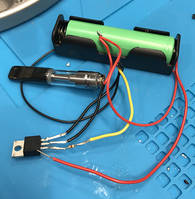
@JCA79B, I tried what you suggested and I was experiencing similar results, although the voltage drop wasn't as bad. Instead of getting 0.1v with the heating element connected, I'm getting roughly 0.6-0.8v. Here's a pic of the setup:

@TomGeorge, here are some pics of the breadboard. I cleaned it up a bit to make it easier to see. I verified that I'm getting the same results.
Here you can see a decent voltage without the heating element:

And then the voltage drop with the heating element:

Here's a close up of the wiring:

Some notes:
Hi,
What is the part number of the MOSFET?
Gate voltage of 3.3V is probably not enough to turn the MOSFET completely ON.
Thanks.. Tom.. ![]()
@TomGeorge, thanks, I’ll get those readings when I get home from work tonight.
The MOSFET is part #: P30N06LE
What was the battery voltage when you were getting 0.6V across the heater?
@JCA79B & @TomGeorge
Here are some more measurements:
With the Original P30N06LE MOSFET:
I tried a IRF3708 MOSFET and was getting a slightly higher voltage to the heating element. Roughly 1.6v versus 1.3v. But still not enough to heat up the element.
Did you say you were able to connect the battery to the heater and get it to work ?
if you did, then you might need re-think how you need to control the FET.
if you are using a USB to power the unit, you have 5v available.
you might also look at getting an IRL FET. one that switches with low input voltage.
OP mosfet is logic level. datasheet
Perhaps the gate resistor is the wrong value or bad. You should be measuring point C right at the gate of the mosfet, not at the esp32 output pin. Gate voltage should be 3.3 volts.
Another possibility is voltage drop in the breadboard which you’ve already seen. But, overall, I question if a 400mAh battery can supply a 2000mAh load for any length of time.
Hi,
It looks like MOSFET cannot turn fully ON with 3.29V on the gate.
What is the gnd to source voltage with gate ON and OFF?
If you disconnect the gate resistor from the ESP32 and connect the resistor to the Lipo positive. So the MOSFET gate is connected to the Lipo positive.
What voltages do you get?
Thanks.. Tom.. ![]()
According to the datasheet for that MOSFET it should be more than on enough for the OP's load. Something else is up.
OP, can you measure: