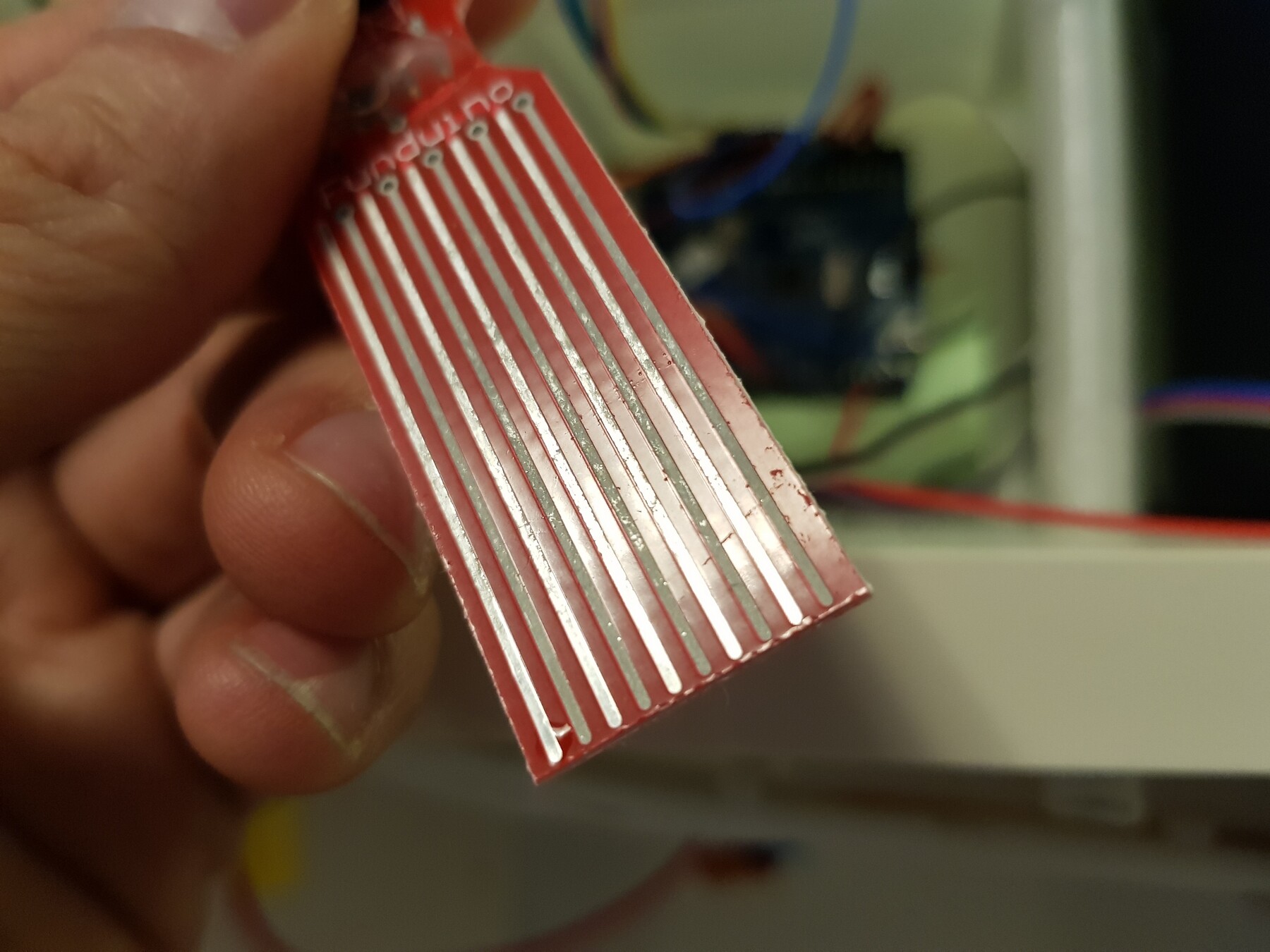
Hi I'm having a relatively common problem with a water sensor, it's corroding. The pin (+voltage) to the sensor is only turned on for 10 millis once a day but after a month (only 30 sensor readings) it's already corroding. Looks like there's about 0.02 V across the pin to ground.
I'm guessing that the constant low voltage to the sensor is causing slow corrosion.
Is there any way to complete block power that's less than 1V, but allow anything over 3V?
those arent hard numbers, just examples of what might work. Hoping there's a simple hardward solution to this, but open to suggestions.
Appreciate any advice and help
(attached is a pic of the corrosion. Not failing yet but it will soon)
Try a gold plated sensor.
Use a DPDT relay to disconnect the sensor when not used.
In the past I have also used a relay to alternately reverse the current flow through the terminals.
Carbon/graphite electrodes are inert, cheaper than platinum too. Not sure if gold is any better than the tin plating on the PCB, I've not heard of it used as an inert electrode (even though it used to be cheaper than platinum).
Right, a relay is a thought. Appreciate all the tips for using a completely different sensor, but mostly curious about the possibility of shutting off the power to the sensor.
Sensing water level would be great, but content with just testing for the presence of water.
Any other hardward solutions anyone can think of? Maybe a basic filtering system for blocking a steady low voltage?
Not sure if this applies, but perhaps this will simulate ideas (if it does apply) -- or at least, maybe, you can apply this knowledge to eliminate this as a possible cause:
Galvanic Corrosion (and the prevention there of):
When dissimilar metals come in contact in water, they tend to corrode. One way to prevent this, is to set up a voltage, across the junction, that cancels the galvanic voltage that develops there.
But, in your case, where is this metallic junction? There ain't one [at least there doesn't appear to be]. So, you're probably asking, "So, ReverseEMF, why this discussion on Galvanic Corrosion?" Glad you asked!
Because, what you have here, perhaps, is a similar situation. Some voltage present, that is causing the corrosion, but, the voltage is not from dissimilar metals. But, if we assume the corrosion is being caused by a voltage, then perhaps the methods for preventing galvanic corrosion apply. I.e. apply a reverse voltage to cancel the existing voltage.
I know -- probably a dumb idea! But, I thought I'd mention it, just in case it sparks creativity, etc.
Use two brass rods or plates, seal soldered wires connected to them. Fighting electro corrosion with reverse voltage will make the design complicated ........
For electro-corrosion (eka plating) material is irrelevant in the ability to corrode. Different materials may be slower or faster to corrode.
I've seen the sensor you have on ebay but do not have an understanding of the circuit provided. Perhaps a forward diode would reduce the corrosion to an acceptable level. I'm thinking the forward drop might be helpful. However there will still be some leakage which may or may not be an issue.
I am in the process of building a water sensor (for leaking plumbing etc). I plan on using 2 stainless steel electrodes (aka #6 screws). However I expect being in water will be an exception so I'm not worried about corrosion.
The old National Semi had a chip called the LM1830N which is a water level sensor. It basically puts a low level AC signal across the electrodes and the internal electronics of the chip let it show up as digital output. There are still some available. I have used this chip for years and only had one or two failures - one was due to a lightning ground strike that took out all of the circuitry including the PC board !! I have one on my above ground spa to ensure that the pump can't run with a low water level and have another to control my sprinkler system when it rains. Both of these instances use 6-32 SS screws as the sensors and have been in service for at least 12 years !! Just a thought !!
#define DOUTPUT__SESNOR_PWR  3  // Arbitrary selection of Digital Pin 3
#define AINPUT__SENSOR_READ  A0 // Arbitrary selection of Analog Pin 0
const long TIMING__ONE_DAY = 86400000L;  // That's how many milliseconds there are in a day

long sensor_reading = 0L;

void doSomethingWithReading(long sensor_reading)
{
  // Put your handler code here!
}

void setup() {
  pinMode(DOUTPUT__SESNOR_PWR, INPUT);  // Power off, for now.
  pinMode(AINPUT__SENSOR_READ, INPUT);
}

void loop() {
  // Turn sensor on and take a reading -- once a day
  pinMode(DOUTPUT__SESNOR_PWR, OUTPUT);  // Get ready to turn the sensor on
  digitalWrite(DOUTPUT__SESNOR_PWR, HIGH);  // Turn it on

  delay(300);  // Wait 300 mS for things to settle [wild guess on that number -- experiment ;) ]

  // Take a sensor reading
  sensor_reading = analogRead(AINPUT__SENSOR_READ);

  // Shutdown the sensor by presenting a High Impedance to the sensor circuit (similar to opening a power switch).
  digitalWrite(DOUTPUT__SESNOR_PWR, LOW);  // Set to LOW to make sure no Pull Ups are active -- just in case (can't be sure what version of IDE is in use).
  pinMode(DOUTPUT__SESNOR_PWR, INPUT);  // Set pin impedance to around 100MΩ
  // Do a digital read on the sensor pin to increase the impedance to 100MΩ (from the lower S/H impedance of an ADC channel)
  digitalRead(AINPUT__SENSOR_READ);

  doSomethingWithReading(sensor_reading);

  // Wait for a day
  delay(TIMING__ONE_DAY);
}
The value of the resistor (in series with the sensor) is probably not correct. And, if the value needs to be greater than 10k, then I suggest adding the capacitor, on the input (see below). The capacitor will present an impedance that is within the suggested range of 0 to 10k. Also, the diode might be a way to snub that 0.02 volts you are reading (try a 1N914 or 1N4148). In fact, you might be able to just add the diode to your existing circuit [but, because I haven't seen how you're actually connecting that sensor to the Arduino, you will have to make adjustments as needed -- but my goal, here, is to offer inspiration.
The 0.2V arises because of the different grounds. The ground in your house's distribution board will be different to some other object put into the ground. The circuits above are neat but the ground pin will corrode, probably faster than the positive one.
Hi,
I have used this type of circuit in an automotive window wash tank, which does not use DC current.
I think I also used stainless wire/rods.
Single 5V DC supply, you don't need +9V and -9V.
MorganS:
The 0.2V arises because of the different grounds. The ground in your house's distribution board will be different to some other object put into the ground. The circuits above are neat but the ground pin will corrode, probably faster than the positive one.
I don't get what you are saying. What different grounds? Also, in my diagrams/accompanying code, the sensor is only energized long enough to take a reading, around 300ms -- and that's once a day. Otherwise, all the Arduino pins are at 100MΩ. Doubtful there would be enough current to cause any corrosion -- even if there are dissimilar grounds. The only current path is through the Arduino inputs -- which are, both, set to Digital Input, and thus at a very high impedance.
The ground symbol on that diagram is the Arduino ground. That's at a different potential to the dirt, unless it's a pot-plant electrically insulated from the ground.
MorganS:
The ground symbol on that diagram is the Arduino ground. That's at a different potential to the dirt, unless it's a pot-plant electrically insulated from the ground.
But, I don't see a current path to the "dirt". The current path is between the probe "prongs"[i.e. out the Arduino "Digital Out" pin, through the resistor, across the water to the "ground" side of the probe, and back to the Arduino's Gnd pin]. Sure, there's possibly a conduction path to Earth Ground, but if so, how is there current flowing in that path?
Unless you mean some kind of leakage current from the power supply ["hot chassis" sort of thing] -- or maybe some capacitive coupling from the mains supply to the Arduino circuit? An easy way to test for that, would be to completely isolate the Arduino by running it off a battery.
mmmatt:
Hi I'm having a relatively common problem with a water sensor, it's corroding. The pin (+voltage) to the sensor is only turned on for 10 millis once a day but after a month (only 30 sensor readings) it's already corroding. Looks like there's about 0.02 V across the pin to ground.
I'm guessing that the constant low voltage to the sensor is causing slow corrosion.
Is there any way to complete block power that's less than 1V, but allow anything over 3V?
those arent hard numbers, just examples of what might work. Hoping there's a simple hardward solution to this, but open to suggestions.
Appreciate any advice and help
(attached is a pic of the corrosion. Not failing yet but it will soon)
Part of your corrosion problem may be caused as you described. But another reason is your sensor has at least two different metals in the water. This will cause an electric current to be generated and will destroy one of the metals over time. Remember your chemistry!
Some have suggested using other metals, all alloys, which doesn't solve the problem. An alloy in water will produce a voltage between the atoms of each metal in the alloy and eventually one metal will be destroyed. Stainless steel takes a while longer, but it will eventually have one of the metal components eaten away. Personal experience.
The ONLY solution is to have PURE metal electrodes. Both of the same metal. Remember in chemistry class, the use of platinum wires in experiments using electricity? Pure titanium may also work. But no alloys. Pure copper is easy to find and may work for you. Find it in soft copper tubing at a hardware store.
Paul_KD7HB:
But another reason is your sensor has at least two different metals in the water. This will cause an electric current to be generated and will destroy one of the metals over time. Remember your chemistry!
Yeah, I considered this, too. But what are the two metals? If you look at the photo, only every other "probe tine" has significant corrosion (i.e. far more corrosion than the other). So, what two metals? The adjacent probe tines? More than likely, all of the probe tines are of the same metallic composition. Then, the copper and the "tin" coating? If so, then why didn't corrosion occur in ALL of the probe tines?
No, more likely because of an external voltage applied across the two sets of tines.