I have a teensy connected to power via a switching regulator that drops voltage from 12v to 5v. The 12V is being used to power a lot of LEDS.
The issue i noticed is that occasionally, i'll try to program the microcontroller without 12v power, using the USB (+5V) as power. THe problem is that that lets ~4.8v to flow backwards out of the regulator, causing my computers USB breaker to trip. Do need to put a diode on the load side of my regualtor to make sure voltage only flows one way (in)?
Well, he basically does have the supply separate in that the LEDs run on 12v and the Arduino on 5v from the regulator. It is hard to say exactly how the regulator will handle 5v on the output side with no input without seeing the schematic of the regulator itself. Putting a diode in the load side (output) of the regulator introduces another 0.7v drop (although a shottky diode is less). I would at least put a diode in series with the input to the regulator (which would also protect it in case you hook the 12v up reversed).
Probably the best solution would be a diode in series with the input to the regulator AND a switch or jumper etc. that allowed you to switch the 5v power between the regulator and the USB supply so there is no chance of a conflict. That protects everybody.
Normally, the teensy is a location that isnt easy to access, so i'm trying to avoid using a switch. But, what your saying is a diode in series with the INPUT of the regualtor would prevent voltage from the USB backflowing past the regulator?
Yes, a diode on the input to the regulator would block anything from going past that, BUT, the problem is I don't know how the regulator itself will handle 5v on the output side with no input. Some regulators can handle it and some will let the magic smoke out. If the regulator is adjustable on the output, you could put a diode in the output side and crank the regulator up .6 volts or so, but be aware that can also create some instabilities in the regulator as well (which can cause really strange things to happen in the system if the regulator goes into oscillation for example :o ) Another option would be to feed the 5v power from the regulator in via a connector similar to This one CP-202a although the danger there is that is the same connector basically as used for raw power so they could get confused when connecting. That connector type though has a built in switch such that when you plug into it, it breaks the connection between two of the 3 pins. Use a different size one - that just happened to be one I had handy for the idea.
gpsmikey:
Well, he basically does have the supply separate in that the LEDs run on 12v and the Arduino on 5v from the regulator. It is hard to say exactly how the regulator will handle 5v on the output side with no input without
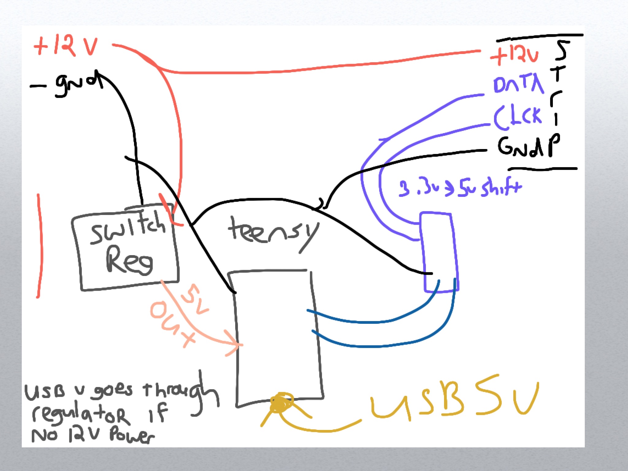
I find it difficult from the diagram and words to understand how the supplies are connected.
A block diagram showing power connections would help.
In the original post he indicated "The 12V is being used to power a lot of LEDS.", however, lets see how your diagram agrees with what he says he has - perhaps I am not reading it correctly.
dlloyd:
Could implement a MOSFET switch to prevent this ... the Arduino does this.
I will try to figure that out, seems handy. I'm assuming the basic idea is when usb vin goes high, the mosfet a a pnp type and turns of the vin supply?
In that image (from UNO schematic) it detects when Vin is available (using the voltage comparator). The comparator goes high when Vin>6.6V. This turns off the P-Channel MOSFET switch, which disconnects the USBVCC.
In your application, could use something similar to disconnect the 5V from the regulator when 5V from the micro USB Jack is detected (if that's what's needed).
Just an idea ....
● If there's 5V from the regulator, USB 5V is turned off
● If there's 5V from the USB, regulator 5V is turned off
● If there's 5V from both, Teensy gets no power.