I'm using Arduino Mega 2560 to light up 20 7-segment LEDs. In addition I'm multiplexing 20 7-segment LEDs. I want it to display 0-9 in digit1 to digit10 and 0-9 in digit11 to digit20. My problem right it is displaying incorrect numbers.
How should I fix this? This is my code.
#define SLOW_CLOCK

int time = 1000;

int a=2;
int b=3;
int c=4;
int d=5;
int e=6;
int f=7;
int g=8;

int digit1 = 13;
int digit2 = 12;
int digit3 = 11;
int digit4 = 10;
int digit5 = 28;
int digit6 = 26;
int digit7 = 25;
int digit8 = 27;
int digit9 = 29;
int digit10 = 31;
int digit11 = 33;
int digit12 = 24;
int digit13 = 22;
int digit14 = 23;
int digit15 = 35;
int digit16 = 37;
int digit17 = 39;
int digit18 = 41;
int digit19 = 43;
int digit20 = 45;

// Define arrays to hold the numbers to display on digits 1 to 10 and digits 11 to 20
int numbers1to10[10] = {
  0, 1, 2, 3, 4, 5, 6, 7, 8, 9
};

int numbers11to20[10] = {
  0, 1, 2, 3, 4, 5, 6, 7, 8, 9
};


void choose_digit(char num) {
  switch(num){
    default:
    // 0 default value
      digitalWrite(a, HIGH);
      digitalWrite(b, HIGH);
      digitalWrite(c, HIGH);
      digitalWrite(d, HIGH);
      digitalWrite(e, HIGH);
      digitalWrite(f, HIGH);
      digitalWrite(g, LOW);
      break;

    case 1:
      digitalWrite(a, LOW);
      digitalWrite(b, HIGH);
      digitalWrite(c, HIGH);
      digitalWrite(d, LOW);
      digitalWrite(e, LOW);
      digitalWrite(f, LOW);
      digitalWrite(g, LOW);
      break;

    case 2:
      digitalWrite(a, HIGH);
      digitalWrite(b, HIGH);
      digitalWrite(c, LOW);
      digitalWrite(d, HIGH);
      digitalWrite(e, HIGH);
      digitalWrite(f, LOW);
      digitalWrite(g, HIGH);
      break;

    case 3:
      digitalWrite(a, HIGH);
      digitalWrite(b, HIGH);
      digitalWrite(c, HIGH);
      digitalWrite(d, HIGH);
      digitalWrite(e, LOW);
      digitalWrite(f, LOW);
      digitalWrite(g, HIGH);
      break;

    case 4:
      digitalWrite(a, LOW);
      digitalWrite(b, HIGH);
      digitalWrite(c, HIGH);
      digitalWrite(d, LOW);
      digitalWrite(e, LOW);
      digitalWrite(f, HIGH);
      digitalWrite(g, HIGH);
      break;

    case 5:
      digitalWrite(a, HIGH);
      digitalWrite(b, LOW);
      digitalWrite(c, HIGH);
      digitalWrite(d, HIGH);
      digitalWrite(e, LOW);
      digitalWrite(f, HIGH);
      digitalWrite(g, HIGH);
      break;

    case 6:
      digitalWrite(a, HIGH);
      digitalWrite(b, LOW);
      digitalWrite(c, HIGH);
      digitalWrite(d, HIGH);
      digitalWrite(e, HIGH);
      digitalWrite(f, HIGH);
      digitalWrite(g, HIGH);
      break;

    case 7:
      digitalWrite(a, HIGH);
      digitalWrite(b, HIGH);
      digitalWrite(c, HIGH);
      digitalWrite(d, LOW);
      digitalWrite(e, LOW);
      digitalWrite(f, LOW);
      digitalWrite(g, LOW);
      break;

    case 8:
      digitalWrite(a, HIGH);
      digitalWrite(b, HIGH);
      digitalWrite(c, HIGH);
      digitalWrite(d, HIGH);
      digitalWrite(e, HIGH);
      digitalWrite(f, HIGH);
      digitalWrite(g, HIGH);
      break;

    case 9:
      digitalWrite(a, HIGH);
      digitalWrite(b, HIGH);
      digitalWrite(c, HIGH);
      digitalWrite(d, HIGH);
      digitalWrite(e, LOW);
      digitalWrite(f, HIGH);
      digitalWrite(g, HIGH);
      break;
  }
}

void setup()
{

#ifdef SLOW_CLOCK
  noInterrupts();
  CLKPR = _BV(CLKPCE);  // enable change of the clock prescaler
  CLKPR = _BV(CLKPS0);  // divide frequency by 2
  interrupts();
#endif;

  pinMode(digit1, OUTPUT);
  pinMode(digit2, OUTPUT);
  pinMode(digit3, OUTPUT);
  pinMode(digit4, OUTPUT);
  pinMode(digit5, OUTPUT);
  pinMode(digit6, OUTPUT);
  pinMode(digit7, OUTPUT);
  pinMode(digit8, OUTPUT);
  pinMode(digit9, OUTPUT);
  pinMode(digit10, OUTPUT);
  pinMode(digit11, OUTPUT);
  pinMode(digit12, OUTPUT);
  pinMode(digit13, OUTPUT);
  pinMode(digit14, OUTPUT);
  pinMode(digit15, OUTPUT);
  pinMode(digit16, OUTPUT);
  pinMode(digit17, OUTPUT);
  pinMode(digit18, OUTPUT);
  pinMode(digit19, OUTPUT);
  pinMode(digit20, OUTPUT);

  pinMode(a, OUTPUT);
  pinMode(b, OUTPUT);
  pinMode(c, OUTPUT);
  pinMode(d, OUTPUT);
  pinMode(e, OUTPUT);
  pinMode(f, OUTPUT);
  pinMode(g, OUTPUT);

  Serial.begin(9600);

}


void pick_digit(int digit) {

  switch(digit) {
    case 1: digitalWrite(digit20, HIGH);
    digitalWrite(digit1, LOW); break;

    case 2: digitalWrite(digit1, HIGH);
    digitalWrite(digit2, LOW); break;

    case 3: digitalWrite(digit2, HIGH);
    digitalWrite(digit3, LOW); break;

    case 4: digitalWrite(digit3, HIGH);
    digitalWrite(digit4, LOW); break;

    case 5: digitalWrite(digit4, HIGH);
    digitalWrite(digit5, LOW); break;

    case 6: digitalWrite(digit5, HIGH);
    digitalWrite(digit6, LOW); break;

    case 7: digitalWrite(digit6, HIGH);
    digitalWrite(digit7, LOW); break;

    case 8: digitalWrite(digit7, HIGH);
    digitalWrite(digit8, LOW); break;

    case 9: digitalWrite(digit8, HIGH);
    digitalWrite(digit9, LOW); break;

    case 10: digitalWrite(digit9, HIGH);
    digitalWrite(digit10, LOW); break;

    case 11: digitalWrite(digit10, HIGH);
    digitalWrite(digit11, LOW); break;

    case 12: digitalWrite(digit11, HIGH);
    digitalWrite(digit12, LOW); break;

    case 13: digitalWrite(digit12, HIGH);
    digitalWrite(digit13, LOW); break;

    case 14: digitalWrite(digit13, HIGH);
    digitalWrite(digit14, LOW); break;

    case 15: digitalWrite(digit14, HIGH);
    digitalWrite(digit15, LOW); break;

    case 16: digitalWrite(digit15, HIGH);
    digitalWrite(digit16, LOW); break;

    case 17: digitalWrite(digit16, HIGH);
    digitalWrite(digit17, LOW); break;

    case 18: digitalWrite(digit17, HIGH);
    digitalWrite(digit18, LOW); break;

    case 19: digitalWrite(digit18, HIGH);
    digitalWrite(digit19, LOW); break;

    case 20: digitalWrite(digit19, HIGH);
    digitalWrite(digit20, LOW); break;

  }
}


void seven_segment() {
  // Loop through digits 1 to 20
  for (int i = 1; i <= 20; i++) {
    // Determine the array index based on the current digit
    int index = (i <= 10) ? i - 1 : i - 11;

    choose_digit((i <= 10) ? numbers1to10[index] : numbers11to20[index]);
    pick_digit(i);

  }

}

void loop() {

  // Display the number on the seven segment display
  seven_segment();

}
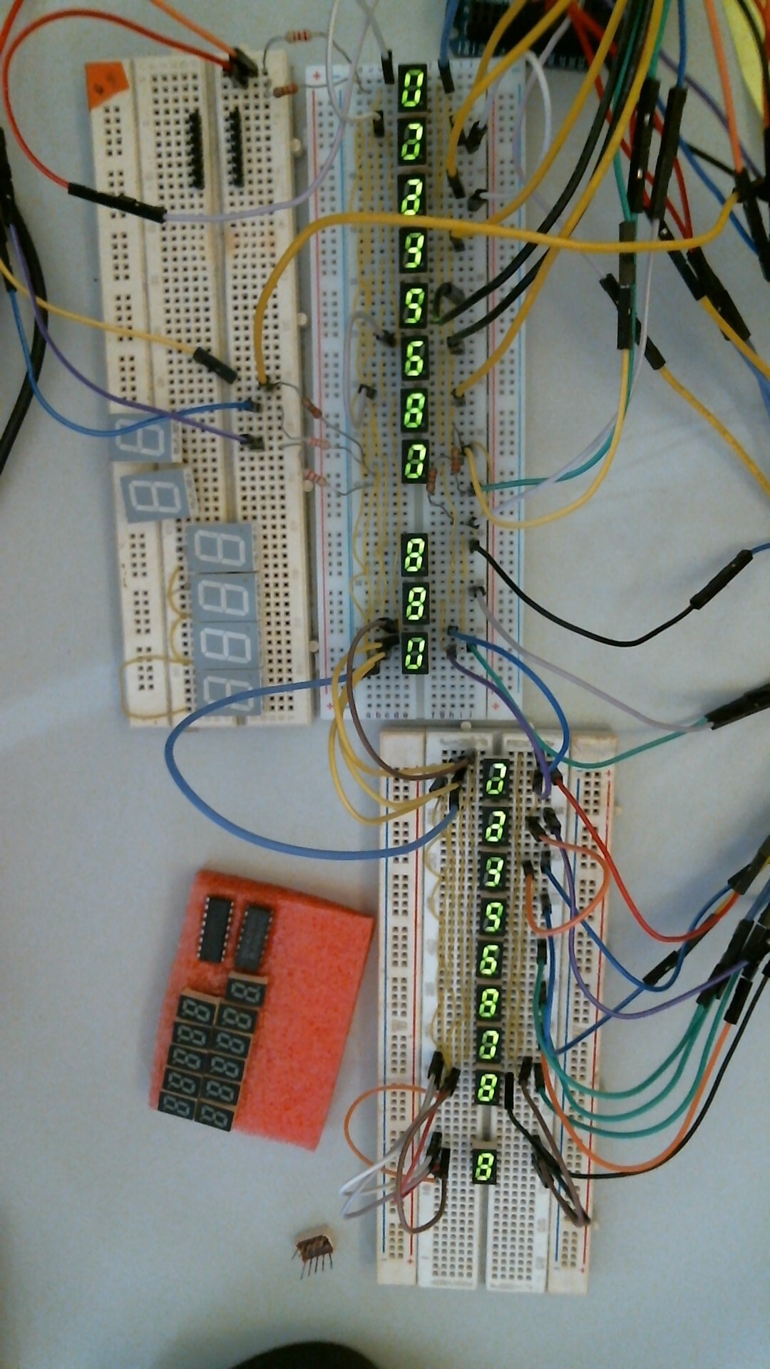
This is the output.