Problem on how to use the NO and NC pins of a relay for two different circuits

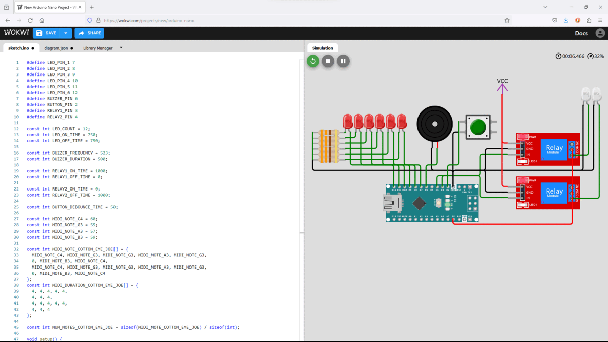
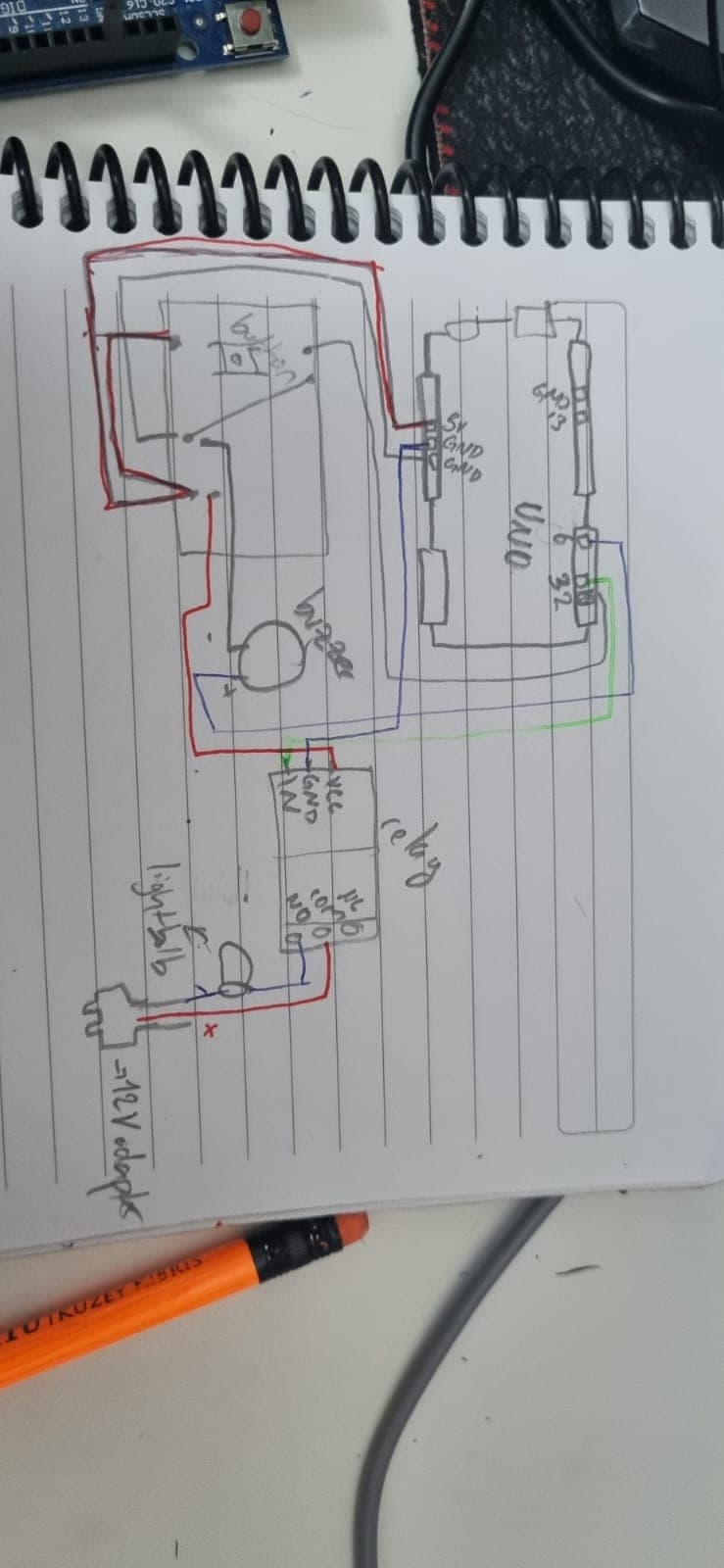
hello, so Im trying to use my relay to be toggled on and off with a switch, when the the circuit is powered for the first time, I want the a lightbulb to turn on, and with the push of a button, I want the lightbulb to turn off and activate the LEDs and the buzzer thats also connected to the relay. (not sure if this is possible but I need to make it work somehow. My math grade(somehow) depends on this. Thanks in advance! Im going to paste my current code. Right now, the button doesnt do anything other than dimming the light on the relay when activated but it used to toggle it but I messed it up somehow.

Thanks in advance.


#define LED_PIN_1 7
#define LED_PIN_2 8
#define LED_PIN_3 9
#define LED_PIN_4 10
#define LED_PIN_5 11
#define LED_PIN_6 12
#define BUZZER_PIN 6
#define BUTTON_PIN 2
#define RELAY1_PIN 3
#define RELAY2_PIN 4

const int LED_COUNT = 12;
const int LED_ON_TIME = 750; 
const int LED_OFF_TIME = 750; 

const int BUZZER_FREQUENCY = 523;
const int BUZZER_DURATION = 500; 

const int RELAY1_ON_TIME = 1000; 
const int RELAY1_OFF_TIME = 0; 

const int RELAY2_ON_TIME = 0; 
const int RELAY2_OFF_TIME = 1000;

const int BUTTON_DEBOUNCE_TIME = 50; 

const int MIDI_NOTE_C4 = 60;
const int MIDI_NOTE_G3 = 55;
const int MIDI_NOTE_A3 = 57;
const int MIDI_NOTE_B3 = 59;

const int MIDI_NOTE_COTTON_EYE_JOE[] = {
  MIDI_NOTE_C4, MIDI_NOTE_G3, MIDI_NOTE_G3, MIDI_NOTE_A3, MIDI_NOTE_G3,
  0, MIDI_NOTE_B3, MIDI_NOTE_C4,
  MIDI_NOTE_C4, MIDI_NOTE_G3, MIDI_NOTE_G3, MIDI_NOTE_A3, MIDI_NOTE_G3,
  0, MIDI_NOTE_B3, MIDI_NOTE_C4
};
const int MIDI_DURATION_COTTON_EYE_JOE[] = {
  4, 4, 4, 4, 4,
  4, 4, 4,
  4, 4, 4, 4, 4,
  4, 4, 4
};

const int NUM_NOTES_COTTON_EYE_JOE = sizeof(MIDI_NOTE_COTTON_EYE_JOE) / sizeof(int);

void setup() {
  pinMode(LED_PIN_1, OUTPUT);
  pinMode(LED_PIN_2, OUTPUT);
  pinMode(LED_PIN_3, OUTPUT);
  pinMode(LED_PIN_4, OUTPUT);
  pinMode(LED_PIN_5, OUTPUT);
  pinMode(LED_PIN_6, OUTPUT);
  pinMode(BUZZER_PIN, OUTPUT);
  pinMode(BUTTON_PIN, INPUT_PULLUP);
  pinMode(RELAY1_PIN, OUTPUT);
  pinMode(RELAY2_PIN, OUTPUT);


  for (int i = 0; i < LED_COUNT; i++) {
    digitalWrite(LED_PIN_1 + i / 2, LOW);
  }

  digitalWrite(RELAY1_PIN, LOW);
  digitalWrite(RELAY2_PIN, LOW);
}

void loop() {
if (digitalRead(BUTTON_PIN) == LOW) {
    while (digitalRead(BUTTON_PIN) == LOW) {}

    digitalWrite(RELAY1_PIN, !digitalRead(RELAY1_PIN));

    delay(50);
  }
}

Welcome to the forum

The preferred method is to post code in a reply rather than to attach it and you can already do that. Please remember to use code tags when you post your code

Incidentally, this may be of interest

To post images etc. you need trust level 1, you can get there by:

  • Entering at least 5 topics
  • Reading at least 30 posts
  • Spend a total of 10 minutes reading posts

Users at trust level 1 can...

  • Use all core Discourse functions; all new user restrictions are removed
  • Send PMs
  • Upload images and attachments
1 Like

I have the answer to this and all your following questions...

Never let your future depend on others.

Your sketch only lights a lamp through relay 1 if the button is pressed. The "dimming" you describe is because you are powering the RELAYS with the Arduino.

leds

diagram.json for WOKWI.COM
{
  "version": 1,
  "author": "Anonymous maker",
  "editor": "wokwi",
  "parts": [
    { "type": "wokwi-arduino-nano", "id": "nano", "top": -43.2, "left": 18.7, "attrs": {} },
    {
      "type": "wokwi-led",
      "id": "led1",
      "top": -176.4,
      "left": -63.4,
      "attrs": { "color": "red" }
    },
    {
      "type": "wokwi-resistor",
      "id": "r1",
      "top": -140.05,
      "left": -105.6,
      "attrs": { "value": "333" }
    },
    { "type": "wokwi-relay-module", "id": "relay1", "top": -134.2, "left": 220.8, "attrs": {} },
    {
      "type": "wokwi-buzzer",
      "id": "bz1",
      "top": -189.6,
      "left": 78.6,
      "attrs": { "volume": "0.1" }
    },
    {
      "type": "wokwi-led",
      "id": "led2",
      "top": -176.4,
      "left": -44.2,
      "attrs": { "color": "red" }
    },
    {
      "type": "wokwi-resistor",
      "id": "r2",
      "top": -130.45,
      "left": -105.6,
      "attrs": { "value": "333" }
    },
    { "type": "wokwi-led", "id": "led3", "top": -176.4, "left": -25, "attrs": { "color": "red" } },
    {
      "type": "wokwi-resistor",
      "id": "r3",
      "top": -120.85,
      "left": -105.6,
      "attrs": { "value": "333" }
    },
    {
      "type": "wokwi-led",
      "id": "led4",
      "top": -176.4,
      "left": -5.8,
      "attrs": { "color": "red" }
    },
    {
      "type": "wokwi-resistor",
      "id": "r4",
      "top": -111.25,
      "left": -105.6,
      "attrs": { "value": "333" }
    },
    {
      "type": "wokwi-led",
      "id": "led5",
      "top": -176.4,
      "left": 13.4,
      "attrs": { "color": "red" }
    },
    {
      "type": "wokwi-resistor",
      "id": "r5",
      "top": -101.65,
      "left": -105.6,
      "attrs": { "value": "333" }
    },
    {
      "type": "wokwi-led",
      "id": "led6",
      "top": -176.4,
      "left": 32.6,
      "attrs": { "color": "red" }
    },
    {
      "type": "wokwi-resistor",
      "id": "r6",
      "top": -92.05,
      "left": -105.6,
      "attrs": { "value": "333" }
    },
    { "type": "wokwi-relay-module", "id": "relay2", "top": -57.4, "left": 220.8, "attrs": {} },
    {
      "type": "wokwi-led",
      "id": "led7",
      "top": -224.4,
      "left": 359,
      "attrs": { "color": "white" }
    },
    {
      "type": "wokwi-led",
      "id": "led8",
      "top": -224.4,
      "left": 378.2,
      "attrs": { "color": "white" }
    },
    {
      "type": "wokwi-pushbutton",
      "id": "btn1",
      "top": -166.6,
      "left": 163.2,
      "attrs": { "color": "green" }
    }
  ],
  "connections": [
    [ "led1:C", "r1:2", "green", [ "v0" ] ],
    [ "led2:C", "r2:2", "green", [ "v0" ] ],
    [ "led3:C", "r3:2", "green", [ "v0" ] ],
    [ "led4:C", "r4:2", "green", [ "v0" ] ],
    [ "led5:C", "r5:2", "green", [ "v0" ] ],
    [ "led6:C", "r6:2", "green", [ "v0" ] ],
    [ "nano:GND.2", "bz1:1", "black", [ "v-28.8", "h-48" ] ],
    [ "led6:A", "nano:7", "green", [ "v57.6", "h28.8" ] ],
    [ "led5:A", "nano:8", "green", [ "v57.6", "h38.4" ] ],
    [ "led4:A", "nano:9", "green", [ "v57.6", "h48" ] ],
    [ "led3:A", "nano:10", "green", [ "v57.6", "h57.6" ] ],
    [ "led2:A", "nano:11", "green", [ "v57.6", "h67.2" ] ],
    [ "led1:A", "nano:12", "green", [ "v57.6", "h76.8" ] ],
    [ "nano:GND.2", "r6:1", "black", [ "v-28.8", "h-240" ] ],
    [ "r6:1", "r5:1", "green", [ "v0" ] ],
    [ "r5:1", "r4:1", "green", [ "v0" ] ],
    [ "r4:1", "r3:1", "green", [ "v0" ] ],
    [ "r3:1", "r2:1", "green", [ "v0" ] ],
    [ "r2:1", "r1:1", "green", [ "v0" ] ],
    [ "bz1:2", "nano:6", "green", [ "v28.8", "h-19.6" ] ],
    [ "nano:3", "relay1:IN", "green", [ "v-19.2", "h67.2", "v-28.6" ] ],
    [ "nano:4", "relay2:IN", "green", [ "v-19.2", "h76.8", "v38.4" ] ],
    [ "nano:GND.2", "relay1:GND", "black", [ "v-28.8", "h57.6", "v-28.8" ] ],
    [ "nano:GND.2", "relay2:GND", "black", [ "v-28.8", "h57.6", "v38.4" ] ],
    [ "nano:5V", "relay2:VCC", "red", [ "v9.6", "h67.2", "v-67.2" ] ],
    [ "relay2:VCC", "relay1:VCC", "red", [ "h-9.6", "v-67.2" ] ],
    [ "led7:A", "relay1:NO", "green", [ "v0" ] ],
    [ "led8:A", "relay2:NO", "green", [ "v0" ] ],
    [ "nano:GND.2", "led7:C", "black", [ "v-28.8", "h211.2" ] ],
    [ "nano:GND.2", "led8:C", "black", [ "v-28.8", "h240" ] ],
    [ "nano:5V", "relay2:COM", "red", [ "v9.6", "h211.2", "v-56.2" ] ],
    [ "nano:5V", "relay1:COM", "red", [ "v9.6", "h211.2", "v-144" ] ],
    [ "nano:GND.2", "btn1:2.l", "black", [ "v0" ] ],
    [ "nano:2", "btn1:1.l", "green", [ "v-38.4", "h19.2", "v-86.4" ] ]
  ],
  "dependencies": {}
}
1 Like

Your program does not tell us how your Arduino pins, LEDs and relays are connected together.

I just realized that I made a doodoo in my code. I was going to use 2 relays but then decided to only use one for the bulb and the others. what Im trying to do is, make a button control the relay. when I push the button, it toggles the leds and then after another push, the lightbulb. I got 2 parts that Im mostly confused with. Firstly, Im trying to figure out if I can power up the lightbulb and the leds etc all with 1 relay. I also connected the lightbulb to a 220V adapter which I connected the positive cable to the COM pin of the relay. Im not sure if that would work with the other components, but it does a great job at lighting the lightbulb. Couldnt figure out a way to connect the LEDs to the relay so I couldnt test it. any suggestions? Im open to anything that doesnt look like a mess cuz Im gonna put it in a kinda slmall space and dont want too many wires to show. thanks in advance

Relays do not supply power. Relays connect an external power source to a load (light bulb).

LEDs take 20mA each. Six x 20 = 120mA... which brings you to...

The simulation does not have "transistor" as a selection, but you should supply power to your LEDs starting from a power supply, through a transistor, to your LED, with the Arduino DIO pins controlling the conducting of the transistors.

You should draw your idea on paper (and post that here). It will convey you idea better. (because your text in both posts is confusing)

Give it a try.

Im making the diagram rn, hopefully it will be better than my explaining skills.
By the way, I couldnt understand what the transitor does. Does it just generate more power somehow? (I just started this stuff no longer than a month ago so I dont know anything)

Each transistor is the regulator and power handler to each LED. Like a faucet controlling water, you (using the Arduino) control the amount of power sent to the LED.

so Im goingto need one transitor per led.
what if I parallel circut the leds? will I need to put two transitors or just one

Yes, for individual LED control.

and I also need to code all of them seperatly right? Itsgonna take up so much so much space oof

Yes.

No more than your current code... same DIO pins... but power comes from an external supply, through the transistors... and as you learn to code, you will learn how to remove redundancy.

so I dont have to plug it to a power source like a socked or smth like that?

This is not a word.

something*

did my best to draw the diagram of the abomination I've made so far. I've been trying to find a way to connect the NC pin to the leds but cant find a way to do it and with what you've said, its only going to get more complicated I think but Ill manage to do it.

now that I think about it, just sending the picture of the circuit would be easier

The drawing indicates you are energizing the relay with the Arduino. That will eventually fail, probably damaging your Arduino.

can you tell me how to power it without relying on the arduino while using the minimum space possible

also I can send the pics of the circuit if it helps. I even took a video with the lightbulb powered on