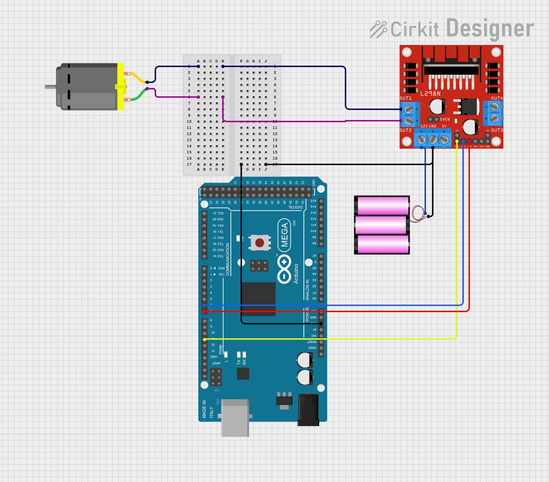
const int motorIn1 = 7;
const int motorIn2 = 6;
const int enableA = 11;  // Pin 10 used for PWM

void setup() {
  // Initialize the motor direction control pins
  pinMode(motorIn1, OUTPUT);
  pinMode(motorIn2, OUTPUT);

  // Set Pin 10 (enableA) for PWM output
  pinMode(enableA, OUTPUT);

  // Set motor direction
  digitalWrite(motorIn1, HIGH);
  digitalWrite(motorIn2, LOW);

  // Configure Timer 1 for 10 kHz frequency on pin 10 (OC1B)
  TCCR1A = 0;  // Clear Timer/Counter Control Register A
  TCCR1B = 0;  // Clear Timer/Counter Control Register B

  // Set Fast PWM mode with ICR1 as TOP
  TCCR1A = (1 << WGM11) | (1 << COM1B1); // Mode 14: Fast PWM, clear OC1B on compare match
  TCCR1B = (1 << WGM12) | (1 << WGM13) | (1 << CS10); // No prescaler

  // Set the top value for 10 kHz PWM
  ICR1 = 1600;

  // Set initial duty cycle to 50%
  OCR1B = 800;  // 50% duty cycle is half speed
}

void loop() {
  // The loop is empty because the setup configuration runs the motor
}
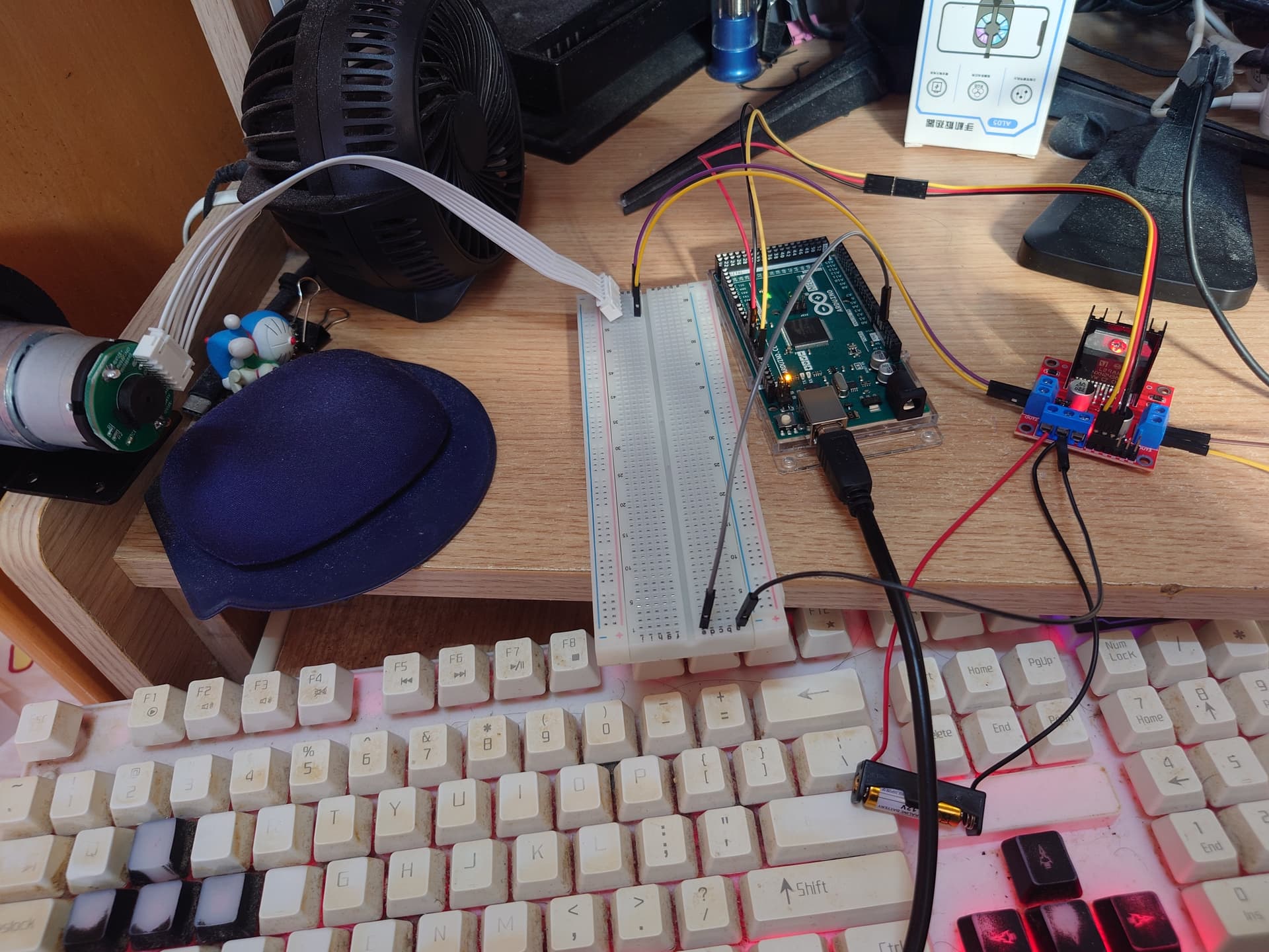
So basically I can't even get the Dc motor to run at all. I asked the manufacturer and they told me I need a PWM frequency of 10khz for it to work and my code did that I think. However nothing works. Can anyone tell me what's wrong with my circuit/code? Thanks in advance.
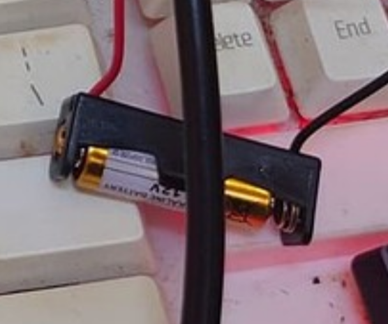
I'm looking right at that dinky little 12V battery. I'd be surprised if it has the amperage to run the motor controller, but there's no way it can supply the 540mA needed to run a single motor. It's just not going to happen.
It looks like they've got the 5V enable jumper in, which, if I remember how those modules work correctly, means that it's using its onboard 5V regulator which is being supplied by the 12V battery. If you look carefully at the picture, you can just see the top of the jumper, and the glow of the LED which would indicate that the 5V supply is up and running.
The issue with the battery is not the only problem.
I tried out your code.
It worked on an Uno R3 after changing the 'enableA' pin back to 10 (as per the comments).
I got a 10kHz signal with 50% duty cycle on pin 10.
On a Uno R3, pin 10 is port B2.
But it did not work on a Mega2560.
On a Mega2560, pin 10 is port B4.
As far as I can see port B2 is not used on the Mega2560.
Nevermind, I think this new code is now okay with mega2560, I have changed it to OC2A. Can you help me to test it again?
const int motorIn1 = 7;
const int motorIn2 = 6;
const int enableA = 10;  // Pin 10 used for PWM

void setup() {
  // Initialize the motor direction control pins
  pinMode(motorIn1, OUTPUT);
  pinMode(motorIn2, OUTPUT);

  // Set Pin 10 (enableA) for PWM output
  pinMode(enableA, OUTPUT);

  // Set motor direction
  digitalWrite(motorIn1, HIGH);
  digitalWrite(motorIn2, LOW);

  // Configure Timer 2 for 10 kHz frequency on pin 10 (OC2A)
  TCCR2A = 0;  // Clear Timer/Counter Control Register A
  TCCR2B = 0;  // Clear Timer/Counter Control Register B

  // Set Fast PWM mode with OCR2A as TOP
  TCCR2A = (1 << WGM20) | (1 << WGM21) | (1 << COM2A1); // Fast PWM, clear OC2A on compare match
  TCCR2B = (1 << WGM22) | (1 << CS20);  // No prescaler

  // Set the top value for 10 kHz PWM
  OCR2A = 159;  // For Fast PWM mode with OCR2A as TOP

  // Set initial duty cycle to 50%
  OCR2B = 80;  // 50% duty cycle is half speed
}

void loop() {
  // The loop is empty because the setup configuration runs the motor
}
I don't think that is true. The usual reason for using a higher PWM frequency is to avoid unpleasant audible noise from the motor. But the motor itself doesn't care much what the PWM frequency is.
I suppose it's possible that a lower PWM frequency could interfere with the encoder circuit in some way.
You seem to have marked the topic as solved. That may discourage forum members from responding because they think you don't need any more help. Better un-mark it!
You've gone from using timer 1 to using timer 2.
Each timer is associated with particular pins, so you can't just change timers and expect it to work on the same pin.
I find the following website useful for learning about operation of the timers:
Thanks for testing again. If that's the case, it should work when I use pin12 right? As pin12 on Arduino mega is OC1B, which would be the same as pin10 on Arduino uno.
const int motorIn1 = 7;
const int motorIn2 = 6;
const int enableA = 12;  // Pin 12 used for PWM

void setup() {
  // Initialize the motor direction control pins
  pinMode(motorIn1, OUTPUT);
  pinMode(motorIn2, OUTPUT);

  // Set Pin 10 (enableA) for PWM output
  pinMode(enableA, OUTPUT);

  // Set motor direction
  digitalWrite(motorIn1, HIGH);
  digitalWrite(motorIn2, LOW);

  // Configure Timer 1 for 10 kHz frequency on pin 12 (OC1B)
  TCCR1A = 0;  // Clear Timer/Counter Control Register A
  TCCR1B = 0;  // Clear Timer/Counter Control Register B

  // Set Fast PWM mode with ICR1 as TOP
  TCCR1A = (1 << WGM11) | (1 << COM1B1); // Mode 14: Fast PWM, clear OC1B on compare match
  TCCR1B = (1 << WGM12) | (1 << WGM13) | (1 << CS10); // No prescaler

  // Set the top value for 10 kHz PWM
  ICR1 = 1600;

  // Set initial duty cycle to 50%
  OCR1B = 800;  // 50% duty cycle is half speed
}

void loop() {
  // The loop is empty because the setup configuration runs the motor
}