Problem with Hardware SPI Communication between MAX31865 and Arduino Mega 2560

Hello,

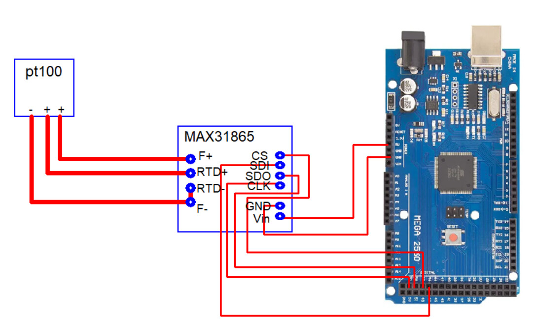
I'm encountering a problem with my setup using a MAX31865 RTD sensor on an Arduino Mega 2560 with an Ethernet Shield (W5100).

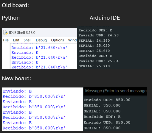
Previously, on older Arduino Mega boards, I was able to use hardware SPI for the MAX31865 and the Ethernet Shield without issues. However, on the new Arduino Mega 2560 boards I've purchased recently, the hardware SPI communication with the MAX31865 stops working.

When I switch to using software SPI, the MAX31865 operates correctly. But as soon as I call Ethernet.begin(mac, ip); to initialize the Ethernet Shield, the MAX31865 stops functioning.

Another unusual detail I noticed is that software SPI communication fails if the sensor’s SDI pin is connected to digital pin 51. When SDI is connected to any other pin, it works as expected.

I have double-checked the hardware connections (even swapping SDI and SDO on the MAX31865) but the problem persists.

Has anyone encountered a similar issue or found a solution to restore reliable hardware SPI communication on the new boards? Any help would be appreciated.

#include <TimeLib.h>
#include <Adafruit_MAX31865.h>
#include <pt100rtd.h>
#include <Ethernet.h>
#include <EthernetUdp.h>
#include <avr/wdt.h>

//sdo=50,sdi=51,clk=52
//MOSI= SDO = 50
//MISO= SDI = 51
//CLK = 52
//SDA=20
//SCL=21
Adafruit_MAX31865 max_1a = Adafruit_MAX31865(48);
Adafruit_MAX31865 max_2a = Adafruit_MAX31865(46);
Adafruit_MAX31865 max_3a = Adafruit_MAX31865(44);
Adafruit_MAX31865 max_4a = Adafruit_MAX31865(42);
Adafruit_MAX31865 max_5a = Adafruit_MAX31865(40);

#define RREF 430.0
#define C2F(c) ((9 * c / 5) + 32)
pt100rtd PT100 = pt100rtd() ;

byte mac[] = {0x90, 0xA2, 0xDA, 0x0D, 0xA0, 0x33};
IPAddress ip(xxx,xxx,xxx,202);  //put your ip here
unsigned int puerto = 3000;
char packetBuffer[UDP_TX_PACKET_MAX_SIZE];
String dataReq;
EthernetUDP udp;

void setup() {

  max_1a.begin(MAX31865_3WIRE);
  max_2a.begin(MAX31865_3WIRE);
  max_3a.begin(MAX31865_3WIRE);
  max_4a.begin(MAX31865_3WIRE);
  max_5a.begin(MAX31865_3WIRE);

  Serial.begin(9600);

  wdt_disable();
  delay(3000);
  wdt_enable(WDTO_4S);
  
  Ethernet.begin(mac, ip);
  udp.begin(puerto);
  delay(1500);

}

void loop() {
  if (udp.parsePacket() > 0) {
        
    udp.read(packetBuffer, UDP_TX_PACKET_MAX_SIZE);
    String datReq(packetBuffer);
    Serial.println(datReq);
        
    uint16_t rtd_1a, rtd_2a, rtd_3a, rtd_4a, rtd_5a,ohmsx100;
    uint32_t dummy ;
    float ohms, Tlut, T ;
    rtd_1a = max_1a.readRTD();
    rtd_2a = max_2a.readRTD();
    rtd_3a = max_3a.readRTD();
    rtd_4a = max_4a.readRTD();
    rtd_5a = max_5a.readRTD();
  
    uint16_t vector[5]={rtd_1a,rtd_2a,rtd_3a,rtd_4a,rtd_5a};
    udp.beginPacket(udp.remoteIP(), udp.remotePort());
    
    for (int i = 0; i < 5; i = i + 1) {
        dummy = ((uint32_t)(vector[i] << 1)) * 100 * ((uint32_t) floor(RREF)) ;
        dummy >>= 16 ;
        ohmsx100 = (uint16_t) (dummy & 0xFFFF) ;
        Tlut  = PT100.celsius(ohmsx100) ;
        
        udp.print(Tlut, 3);
        if (i < 4) {
          udp.print(",");
        } 
    }
    udp.println("");
    udp.endPacket();
  }
  wdt_reset();  
}

Thank you!

My eyes are a bit on the weak side and I cannot see what you have. Post an annotated schematic showing exactly how you have wired this. Show all hardware, connections and power sources.

1 Like

Hardware:

The Arduino is connected to the computer via USB and to the router via the LAN port.

Connection Diagram:
MAX 31865 -----> Arduino Mega
VIN ----------> 5V
GND ----------> GND
CLK ----------> D52
SDO ----------> D50
SDI ----------> D51
CS ----------> D48

Here is a simplified version of the code corresponding to the setup shown in the images:

#include "RTClib.h"
#include <TimeLib.h>
#include <Wire.h>
#include <Adafruit_MAX31865.h>
#include <pt100rtd.h>
#include <Ethernet.h>
#include <EthernetUdp.h>
#include <avr/wdt.h>

RTC_DS3231 rtc;
bool horaEstablecida = true, relojConectado = true;

//MOSI= SDO = 50
//MISO= SDI = 51
//CLK = 52
//CS = 48
//HARDWARE SPI
Adafruit_MAX31865 max_1a = Adafruit_MAX31865(48);

#define RREF 430.0
#define C2F(c) ((9 * c / 5) + 32)
pt100rtd PT100 = pt100rtd() ;

byte mac[] = {0x90, 0xA2, 0xDA, 0x0D, 0xA0, 0x33};// direcciĂłn MAC.
IPAddress ip(xxx,xxx,xxx,202); // 
unsigned int puerto = 3000;
char packetBuffer[UDP_TX_PACKET_MAX_SIZE];
String dataReq;
EthernetUDP udp;

void setup() {

  max_1a.begin(MAX31865_3WIRE);

  Serial.begin(9600);

  wdt_disable();
  delay(3000);
  wdt_enable(WDTO_4S);
  
  Ethernet.begin(mac, ip);
  udp.begin(puerto);
  delay(1500);

}

void loop() {
  float inicio=millis();
  uint16_t rtd_1a,ohmsx100;
  uint32_t dummy ;
  float ohms, Tlut, T ;
  rtd_1a = max_1a.readRTD();

  Serial.print("SERIAL: ");
  dummy = ((uint32_t)(rtd_1a << 1)) * 100 * ((uint32_t) floor(RREF)) ;
  dummy >>= 16 ;
  ohmsx100 = (uint16_t) (dummy & 0xFFFF) ;
  
  Tlut  = PT100.celsius(ohmsx100) ;
  Serial.println(Tlut ,3) ; 
                         
  if (udp.parsePacket() > 0) {
        
    udp.read(packetBuffer, UDP_TX_PACKET_MAX_SIZE);
    String datReq(packetBuffer);
    Serial.println("Recibido UDP: "+datReq);
    udp.beginPacket(udp.remoteIP(), udp.remotePort());
        
    udp.println(Tlut, 3);
    Serial.print("Enviado UDP: ");
    Serial.println(Tlut);
    udp.endPacket();
     
  }else{
  float fin=millis();
  float delta=(fin-inicio);
  if (delta<1000){
  delay(1000-delta);
  }}
  
  wdt_reset();  
  
}

Python script to read the data via ethernet:

from socket import *
from time import sleep

cliente_socket=socket(AF_INET,SOCK_DGRAM)
timeout=2
cliente_socket.settimeout(timeout)
ip="xxx.xxx.xxx.202"
puerto=3000
print('Iniciando cliente UDP...timeout: '+str(timeout)+'s')
print('IP: '+ip)
print('Puerto: '+str(puerto))

while(True):
    try:
        data1="E" 
        print('Enviando: '+data1)
        cliente_socket.sendto(data1.encode(),(ip,puerto))
    except:
        mensaje='FALLO ENVIO '+ip

    try:
        rec_data,addr=cliente_socket.recvfrom(2048) 
        if str(addr[0])==str(ip):
            print("Recibido: "+str(rec_data))
        else:
            print('DISPOSITIVO OFFLINE '+ip)
    except:
        print('DISPOSITIVO OFFLINE '+ip)
    
    sleep(1)

Results

Issue with Hardware SPI:

*Hardware SPI on the new board does not work, even without Ethernet setup.
*Software SPI on the new board only works without Ethernet setup

To make it work with Software SPI, I used the following modifications:
Connection:
MAX 31865 -----> Arduino Mega
VIN ----------> 5V
GND ----------> GND
CLK ----------> D52
SDO ----------> D50
SDI ----------> D46
CS ----------> D48

Code:

...

//SOFTWARE SPI
Adafruit_MAX31865 max_1a = Adafruit_MAX31865(48,46,50,52);

...

void setup() {

  max_1a.begin(MAX31865_3WIRE);

  Serial.begin(9600);

  wdt_disable();
  delay(3000);
  wdt_enable(WDTO_4S);
  
  //Ethernet.begin(mac, ip);
  //udp.begin(puerto);
  delay(1500);

}

...

Summary:

I need to either:

  1. Fix Hardware SPI, or
  2. Make Software SPI work together with the Ethernet connection.

Thanks!

Missing annotated schematic as requested in post 2. Word salads do not make a schematic. You can get free schematic capture from KiCad for free. It is a complete package and will take you through making the Gerbers for a PCB.

I hope this works for you

FOR HARDWARE SPI:

FOR SOFTWARE SPI:

I didn't see in your code where pin 53 was set as an output, even if was not used. In Arduino stream documentation it says"The Arduino board communicates with the shield using the SPI bus. This is on digital pins 11, 12, and 13 on the Uno and pins 50, 51, and 52 on the Mega. On both boards, pin 10 is used as SS. On the Mega, the hardware SS pin, 53, is not used to select the Ethernet controller chip, but it must be kept as an output or the SPI interface won't work."
Hope this helps.
Unlike

1 Like

I tried setting pin 53 as an output, but it didn't change anything. I also couldn’t get it to work with the Hardware SPI configuration. However, I found a solution using Software SPI. Apparently, with these new boards you can connect the MAX31865 to any of the Arduino’s digital pins—except for pins 50, 51, 52, or 53 when using the Ethernet shield. For example:

Connection Diagram:
MAX 31865 -----> Arduino Mega
VIN ----------> 5V
GND ----------> GND
CLK ----------> D30
SDO ----------> D32
SDI ----------> D34
CS ----------> D28

Code:

#include "RTClib.h"
#include <TimeLib.h>
#include <Wire.h>
#include <Adafruit_MAX31865.h>
#include <pt100rtd.h>
#include <Ethernet.h>
#include <EthernetUdp.h>
#include <avr/wdt.h>

// SOFTWARE SPI (cs,sdi,sdo,clk)
Adafruit_MAX31865 max_1a = Adafruit_MAX31865(28,34,32,30);

#define RREF 430.0
#define C2F(c) ((9 * c / 5) + 32)
pt100rtd PT100 = pt100rtd() ;

byte mac[] = {0x90, 0xA2, 0xDA, 0x0D, 0xA0, 0x33};// direcciĂłn MAC.
IPAddress ip(192, 168, 100, 202); // 
unsigned int puerto = 3000;
char packetBuffer[UDP_TX_PACKET_MAX_SIZE];
String dataReq;
EthernetUDP udp;

void setup() {

  max_1a.begin(MAX31865_3WIRE);

  Serial.begin(9600);

  wdt_disable();
  delay(3000);
  wdt_enable(WDTO_4S);
  
  Ethernet.begin(mac, ip);
  udp.begin(puerto);
  delay(1500);

}

void loop() {
  float inicio=millis();
  uint16_t rtd_1a,ohmsx100;
  uint32_t dummy ;
  float ohms, Tlut, T ;
  rtd_1a = max_1a.readRTD();

  Serial.print("SERIAL: ");
  dummy = ((uint32_t)(rtd_1a << 1)) * 100 * ((uint32_t) floor(RREF)) ;
  dummy >>= 16 ;
  ohmsx100 = (uint16_t) (dummy & 0xFFFF) ;
  
  Tlut  = PT100.celsius(ohmsx100) ;
  Serial.println(Tlut ,3) ; 
                         
  if (udp.parsePacket() > 0) {
        
    udp.read(packetBuffer, UDP_TX_PACKET_MAX_SIZE);
    String datReq(packetBuffer);
    Serial.println("Recibido UDP: "+datReq);
    udp.beginPacket(udp.remoteIP(), udp.remotePort());
        
    udp.println(Tlut, 3);
    Serial.print("Enviado UDP: ");
    Serial.println(Tlut);
    udp.endPacket();
     
  }else{
  float fin=millis();
  float delta=(fin-inicio);
  if (delta<1000){
  delay(1000-delta);
  }}
  
  wdt_reset();  
  
}