Problem with relay

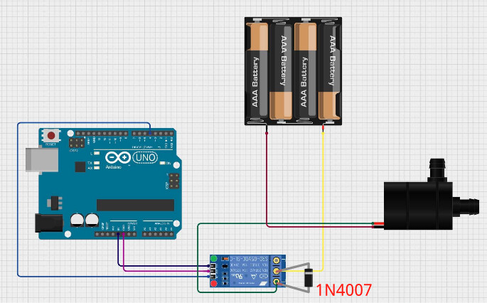
Hi, I recently started my adventure with arduino and for one of my first projects I decided to make a plany watering system. However, I encountered a problem while creating it. The issue is that when I have the whole system connected and I fire off the code that changes the states of the pin in a loop along with a delay, the relay sort of bypasses the delay because it shuts off momentarily when turned on. When the relay has no load, it works flawlessly and turns on/off every two seconds. There is also no problem with operation when the only part of the code is to set the pin to a low state to turn the relay on, then it also works without a problem. As for the relay, it is the SRD-5VDC-SL-C (it a module from here: Buy Relay 5V 10A/250VAC Botland - Robotic Shop). I have included the schematic diagram in the attachment (an arduino is powered from a computer by the usb). What could be the reason for this behavior?

#define pompa 5

void setup() {
  pinMode(pompa, OUTPUT);
  digitalWrite(pompa, HIGH);
}

void loop() {
  digitalWrite(pompa, HIGH);
  delay(2000);           
  digitalWrite(pompa, LOW);
  delay(2000);
}

Hi @kraszor ,

Let's see if you can get closer to the solution by parts.

  1. The startup issue: The pins, for microcontroller security issues, after rebooting start in a LOW tristate configuration, as I recall, that means that when you execute the

pinMode(pompa, OUTPUT);

you are already sending a LOW. To avoid this invert the two setup() lines order, first the digitalWrite, next the pinMode, so when you activate the pin in OUTPUT mode it will be presenting a HIGH condition.

The second part might be related to the characteristics of the relay used, is seems not to be optocupled, so using a motor might filter some noise in the circuit. For starters you've got a 6V power source for your pump, that relay model stands a voltage input of 120% of nominal specification, it means is tolerates 5v*120% = 6v. Disconnect the relay power source from the Arduino and connect it to the battery pack appropiately (that includes the ground must be common...).

Good Luck!
Gaby.//

Thank you for your answer. But I am not sure if I understand. Isn’t a relay with a coil an element that separates the circuits? I don’t understand how can pump affect the arduino. Is it something related to EMI?

Hi @kraszor,

No, the relay is an element to separete mainly the load, so to give you the chance to move a bigger load with a smaller signal.

In the case of this pump what are you getting? The command circuit with low power (from the Arduino port), and a coil (as rightly noted by you) to activate the relay... on the other hand a bigger power (from your power bank) and a coil (your pump motor)... yes, it's better to separate them, you might be having EMI issues.

Good Luck!
Gaby.//

And sorry, my mistake, in my previous answer I shoul have stated...

Gaby.//

@kraszor
Your diagram shows the relay connected to pin 4 but you sketch uses pin 5.
Which one is correct?

It should be connected to pin 5

How do you know this? Does the LED blink off then come back on?
How long is momentarily, 10ms, 50ms, 100ms?

There is an led on the relay module, and instead of turning on and staying lit for 2 seconds (time of the delay) it turns off nearly in the same moment

I will probably power the relay from batteries, but could you explain to me what is a difference between separating load and separating a circuit with a load (I mean this one with batteries and a pump)?

Does it continually do that or does the sketch stop working

Gaby,
I think you are confusing 2 different things. The relay coil is rated for 5V and may well tolerate 6V, but that has nothing to do with the supply to the motor, which is not connected in any way to the relay coil. The contacts can undoubtedly work with a much higher voltage.

Yes, it does.

What does this mean? Why 'no'? The relay separates the circuits, including allowing a small signal to control a large load, and providing isolation between the two.

I agree. However, I think we established that the load and the Arduino are separated by the relay, which leaves poor layout or wiring as a possible cause of problems. @kraszor , please can you post some photos clearly showing the layout of your project?

It continually does that

Try putting a diode across the relay contacts like this
image

Hi @PerryBebbington ,
Thank you for your input and surely the answer to @kraszor deserved a more elaborated redaction, let's see...

The main ideas I'm attempting to give are easy ways to rule out problems in that very simple schematic @kraszor sent.
So instead of going the expensive path I tried to re-elaborate what he has...

A new isolated power source for the relay? No need, the datasheet states specifically (I'm not guessing it) the coil tolerance of 6V, so removing any possibility of the relay coil interfering is as easy as removing the cable from the Arduino and connecting it to his 6V (4 batteries) power bank. Insurance for free.

Optocupler for the signal?? No need unless everything else free fails.

Because you 're right the device isolates electrically the circuits, the one driving the coil from the higher values of the one providing for the main load, but here you have a coil inducing electromangnetic power to drive the contacts, contacts that close and become a conductor of a circuit driving higher current for a pump motor... The way to go is always isolate, and in this case not only to drive a higher load with a weaker signal provider, but to keep any spureous signals out.

If it's EMI he now has 2 roads (let's take out the gnd cable issue now... but no, we shouldn't) from his Arduino to the relay, cutting them down to 1 doesn't seem a bad start... next thing I would ensure is he's using an Optocupler version of those relays, as this one doesn't explicit name this attribute, checkin the provider's site.

So putting this clearly enough: in my humble opinion, having the relay indepentently powered, with a signaling isolation solution, not an electric signal conected to the MCU... yes, it's a complete separation of circuits.

Then, if everything fails...

Good Luck once again.
Gaby.//

Hi, @kraszor
Welcome to the forum.

Can you please post some pictures of your project?
So we can see your component layout.

Do you have a DMM? Digital MultiMeter?

What is the load?
Can you please post a link to data/specs of the load?

Thanks.. Tom.. :grinning: :+1: :coffee: :australia:

@TomGeorge @PerryBebbington
Uploading: IMG_3671.jpeg…


The load is this pump or very simmilar: https://5.imimg.com/data5/IQ/GJ/PF/SELLER-1833510/dc-mini-submersible-water-pump.pdf

Yes, I have a DMM

Thanks for the photos.
At the moment I don't see anything that causes me concern, so I am going to watch this topic and see what others suggest, but at the moment I don't have any ideas for you to try. If I think of anything I'll be back.

Did you try the diode yet?