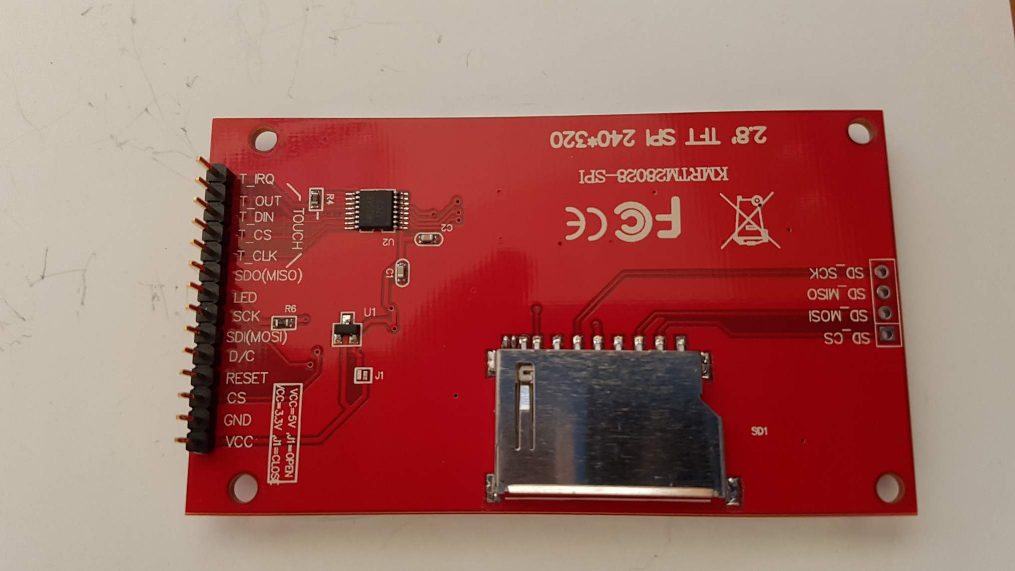
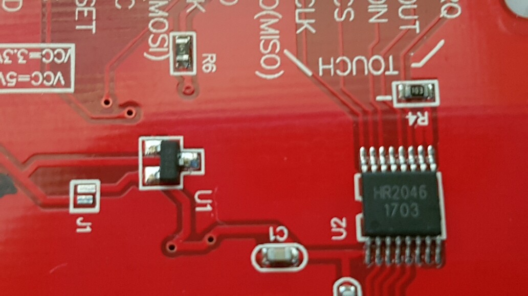
And I received the display in pictures 1-3.
I connected the display as pictur 4, with nano.
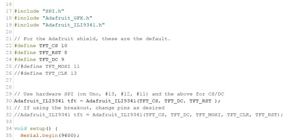
The connections as recommended in the example graphicstest.ino, Figure 5.
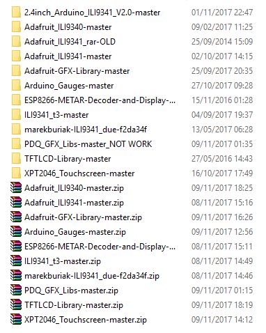
I used all the possible libraries I found on Google, according to Figure 6.
Still unable to display anything on the screen.
Does anyone have any idea how to solve the problem?
Go on. I have replied to many of your questions.
Both Bodmer and I have advised using 3.3V logic.
We have pointed to libraries, tutorials, examples, wiring diagrams, ...
You are not alone. Many people are obsessed with using 5V logic regardless of advice to use level shifters. They all end up with 3.3V and success. Or remain stubborn and fail.
Adafruit examples omit the RST argument in the constructor. Add the RST argument and everything will work.
If you are too stubborn to use the correct constructor, you must add a 3.3V pullup on the RST line.
I tried all the possibilities that are offered in all the links.
The RST and all 5 connections, I hooked up to 3.3 and 5V, with a resistors of 1.2 kHom and without.
The description of the item says that it is possible to connect 5 or 3.3 volts, which did not help.
You need at least 6 channels for shifting SCK, MOSI, TFT_RST, TFT_CS, SD_CS, T_CS if you want to use TFT, SD, XPT2046.
MISO will be at 3,3V levels anyway. I would use a small series resistor in the MISO line and T_IRQ line.
The CD4050 has got 6 channels in one chip. Other buffer chips are available.
Your Ebay link does not look suitable for level shifting SPI signals but it might be ok.
Seriously, many people have used 5V Arduinos and SPI ILI9341 with appropriate level shifting.
Life is simpler with Zero, Due, ..., ESP8266, ESP32, ...
Go on. Look at Bodmer's TFT_ESP library. Look at his advice.
I am guessing that English is not your first language. This is an English language Forum.
If you reveal your country and language, people might try to write replies that are easier for "Google Translate" to understand.
There seems little point in buying a display with SD cage and Touch controller if you don't use them.
And I suggested the lines that need shifting from 5V to 3.3V. Six channels in a Hex buffer chip.
MISO and T_IRQ are 3.3V signals. A 5V AVR will be able to read 3.3V ok.
Yes, you could shift these two signals from 3.3V to 5V if you want. Needing another two level shifters.
I purchased some bidirectional shifters a while ago. I have never tried them. Do they work ok with a high speed SPI bus? It seems a lot easier to stick with 3.3V GPIO like ARM or ESP.
You can use resistor dividers for 5V to 3.3V. There is no need for anything on MISO but a 2k2 series resistor will not upset the read and act as safety if someone sets MISO as OUTPUT by mistake.
apparently these chips can go from from 2Mbps to 24Mbps, I have no idea on what condition
while the adafruit lib sets the spi to SPI_CLOCK_DIV2 => 8Mhz on a arduino mega
actually I've seen the adafruit demo working fine on several occasions, but I can never achieve any stability
I suspected the reset pin on the display not beeing initialized properly, also I noticed the screen had to be powered with 5 volds(having his own 3v regulator)
I noticed ripple on the data lines of yf04e/yf08e I use, so I ordered some smd capacitors to solder them as close as possible, and a 10k pull down resistor so their OE pin is low on start, but I am not sure if it will help
I guess I'll do it with simple voltage divider, but I foudn the ic beeing a more elegant way, and damned I payed for these
I tried the connection to ESP, and did not help either.
I tried with the library TFT_ILI9341_ESP , and with the new library TFT_eSPI,
I have connected as recommend in file User_Setup.h
And I also changed the RST according to the recommend and did not solve the problem.
I'm really desperate, and it seems to me that the display was screwed up.
Your TSX0108E buffers should be plenty fast enough for a Mega2560. And your wiring looks correct.
The 3.3V MISO signal is driven push-pull by TFT, SD or XPT2046. The TSX0108E is high speed.
The 3.3V T_IRQ signal is open-drain (as I remember). Speed is not critical.
I would really like to see your Adafruit_ILI9341 constructor. The Adafruit examples omit the RST argument.
I am fairly certain that I have one of these chips. I might make a 5V adapter shield if I am feeling keen.
I have never seen the need for 5V GPIO. I possess a Mega2560 but only used it with 5V compatible shields.