Problem with using microswitches to measure time intervals

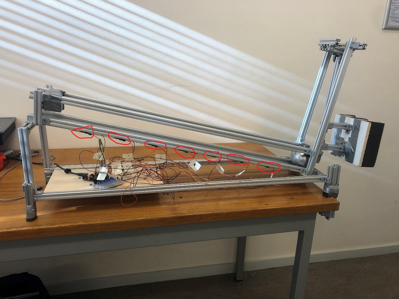
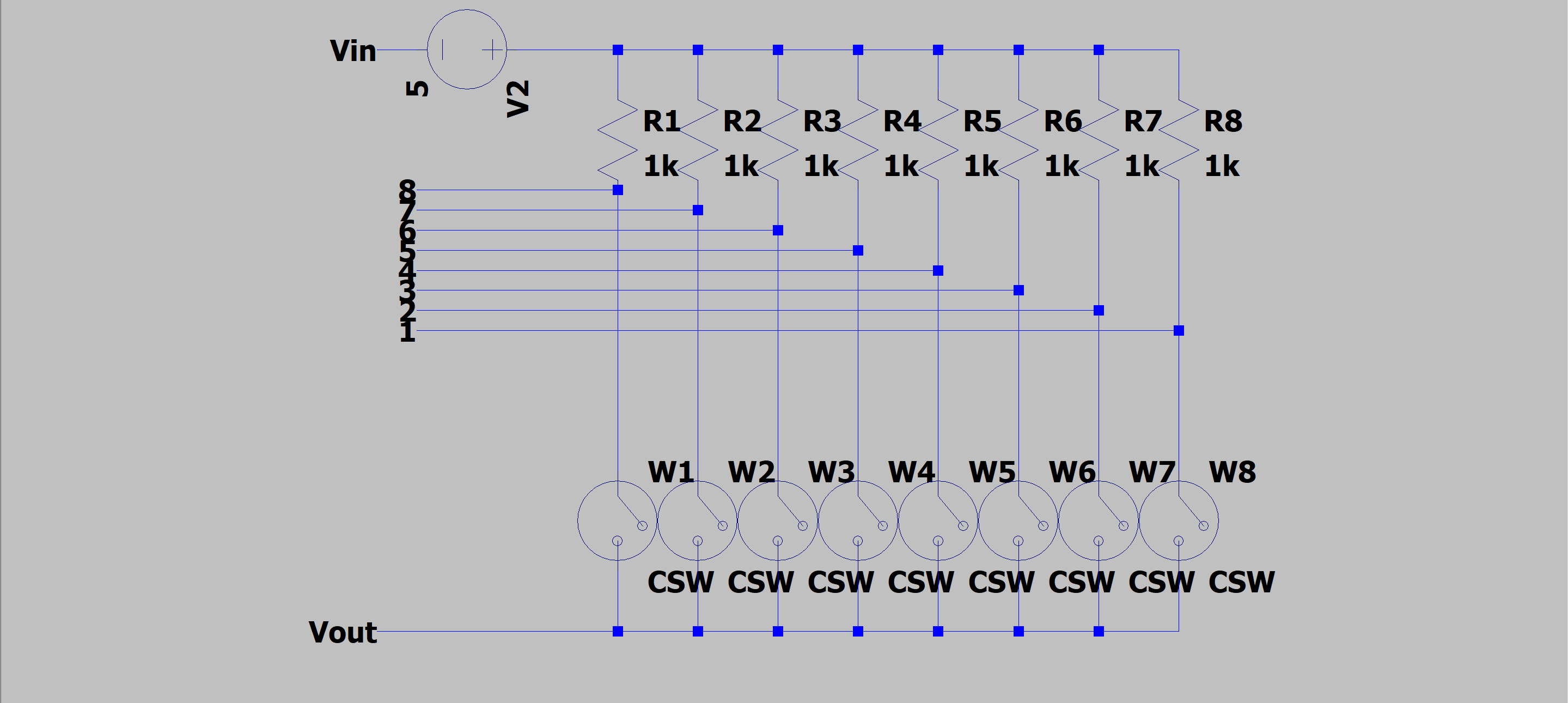
For a school project we use 8 microswitches ( Omron D3V-164-2A5 Microschakelaar 250 V/AC 16 A 1x aan/(uit) 1 stuk(s) Bag kopen ? Conrad Electronic ). We placed the switches parallel with each other like in the following scheme.


We are rolling a cilinder over a hill and have placed the a microswitches in between with a distance of 11cm in between. The time between the activation of the switches (so when switch 2 gets activated after switch 1 is activated) is at minimum 90ms.
The problem we are having is when reading the 8 digital pins out, there is a lot of wordless data coming out. We found that the jittering of the microswitches is at max 1ms. A lot of the times we get values like 5ms and then 184ms for example. We have tried adding leds (diodes) on both ends of the switches, so 16 leds, but then the code did become crazy and kepty printing 12us for the timing between switches. We also have used a capacitor 0.1uF for every switch, unfortunatly that didn't work either.
We have rewritten the code multiple times and that also didn't work. So we are at a point that we don't know how to solve the problem anymore.
We use the following code:

int pinSwitch[8] = {3,4,5,6,7,8,9};

unsigned long timestamp[7]={0,0,0,0,0,0,0};

int pinnumber=0;

unsigned long timeTaken[6]={0,0,0,0,0,0};

void setup() {
  // put your setup code here, to run once:
  for (int i=0;i<7;i++){
    pinMode(pinSwitch[i], INPUT);
  }
  Serial.begin(115200);
}

void loop() {
  // put your main code here, to run repeatedly:
 if (digitalRead(pinSwitch[pinnumber])==0){
    timestamp[pinnumber]=micros();
    pinnumber++;
 }

 if (micros()-timestamp[0]>=5000000 && timestamp[0]!=0 || pinnumber>6){
    printTime();
    resetsystem();
 }
}

unsigned long printTime(){
  for (int i=0;i< (pinnumber-1);i++){
    Serial.print("Switch ");
    Serial.print(i+1);
    Serial.print(" : ");
    Serial.println(timestamp[i]);
  }

  for (int i=0;i<pinnumber-2;i++){
    timeTaken[i]=timestamp[i+1]-timestamp[i];
    Serial.print("Time from switch ");
    Serial.print(i+1);
    Serial.print(" to switch ");
    Serial.print(i+2);
    Serial.print(" :");
    Serial.println(timeTaken[i]);
  }
}

void resetsystem(){
  for (int i=0; i < 7; i++){
    timestamp[i]=0;
  }
  for (int i=0;i < 6;i++){
    timeTaken[i]=0;
  }
  pinnumber=0;
  Serial.println("Ready for next measurement");
  delay(1000);
}

We hope that any of you see you the problem or has some suggestions, because we don't know what to do anymore at this point in time.

And what is your problem?

Does the setup work on the bench ?

How about using one input and recording the time stamps when each switch goes low.

  • You only have 7 switches but have 8 elements.

  • You should be looking at when there is a change in state, not at the switch levels.
    For debounce, scan switches every 50ms looking for a change in state.

  • Is this your logic ?


if ((micros()-timestamp[0]>=5000000) && (timestamp[0]!=0 || pinnumber>6))

unsigned long printTime(){

OR

void printTime(){

With 6 elements in the array numbered from 0...5 the i<7 test isn't quite right.

This bit looks like it could work fine, unless pinnumber counts above 5. It should probably protect against that:

Since the indexing on pinnumber is critical and there look like issues, I'd probably call a function in loop(){} to periodically report on the state of the system:

void report(){
  const uint32_t interval = 1000;
  static uint32_t last = 0;
  uint32_t now = millis();
  if(now - last >= interval){
    last = now;
    Serial.println(pinnumber);
  }
}
2 Likes

The logic used needs neither debouncing nor official state change detection.

Once a switch is seen to be closed, a time is noted and the logic moves on to the next switch. That will react to the next switch as fast as possible. By the time the switch is important again, we can say the switch is open and any bouncing has long ceased.

Or that's what it should do, so for now it is a matter of getting that simple logic to function.

a7

2 Likes

I made a few harmless? changes to the OP's sketch.

I replaced micros() with millis(). I operate on a different time scale. :expressionless:

I used INPUT_PULLUP pin mode, as I am too lazy to wire bunch of resistors.

I changed the reporting test, viz:

// if (millis()-timestamp[0]>=5000000 && timestamp[0]!=0 || pinnumber>6){
  if (pinnumber > 6) {

rather than see what that was trying to do.

I printed the pinnumber to find my own error - wired 2 - 8 instead of 3 - 9, haha.

Pressing the buttons yields

Ready for next measurement
1
2
3
4
5
6
7
Switch 1 : 14721
Switch 2 : 15754
Switch 3 : 16671
Switch 4 : 17589
Switch 5 : 18438
Switch 6 : 20304
Time from switch 1 to switch 2 :1033
Time from switch 2 to switch 3 :917
Time from switch 3 to switch 4 :918
Time from switch 4 to switch 5 :849
Time from switch 5 to switch 6 :1866
Ready for next measurement

a7

2 Likes

:wink:

  • Yes, one needs to always use debounce and state change detection in coding, otherwise in life it will kick you in the pants :sunglasses:

could you use Hall Effect switches? helps with the problems of switch bounce

Switch bouncing does not enter into this.

Th printTime() function had a few errors in the for loop limits which only meant some things it knows weren't being printed. I use 0 as a prefectly good number, so I don't add 1 to fake the printing. It makes the logic less confusing. To me.

unsigned long printTime(){
  for (int i = 0; i < pinnumber; i++){
    Serial.print("Switch ");
    Serial.print(i);
    Serial.print(" : ");
    Serial.println(timestamp[i]);
  }

  for (int i = 0; i < pinnumber - 1; i++) {
    timeTaken[i] = timestamp[i + 1] - timestamp[i];
    Serial.print("Time from switch ");
    Serial.print(i);
    Serial.print(" to switch ");
    Serial.print(i + 1);
    Serial.print(" :");
    Serial.println(timeTaken[i]);
  }
}

a7

1 Like

  • The OP labels the common on the switches Vout
  • Do you have Vout connected to GND .
  • Do you have 7 or 8 switches.
  • Input pin D1 is used for communications.
  • Time to have an accurate schematic, please supply one that matches your sketch.
2 Likes

Yes, I expected it to be the issue, but the way it cleverly switches over to the next sensor at the first signal makes it as responsive as possible and robust against bouncing. Then I saw the confusing indexing issues.

We have thought about it, but then debouncing becomes more of a problem when we want to put the data in an array. The bouncing now isn't a problem because a switch is only listened to once. When we the switches in serie we need to add an extra delay because of the bouncing. So unfortunatly we have tried it without sudfficient results and did go back to this parallel setup.

The indexing has been right in the past, but we removed switches as we expected it could be the problem. We haven't updated it very well lately indeed, but when we did, it didn't matter with the results. But here an updated schematic also.

1 Like

Please post the latest code you are using, and describe the problems you are having.

1 Like

We removed 1 switch indeed. I remembered we used 8, but at last minute we decided to now go for 7 since we removed the switch connected to digital pin 2. I forgot I pasted the code we used for the 7 switches.
I also see that in the code I pasted I have indeed removed the delay after each reading each switch. We have had a delay(10) (so 10ms) in the past in the first if statement of the loop. So I will give the full updated code we are going to try tomorrow. To be honest I don't think it will change anything since we have tried it in the past.

The switches are wired so that they are always high (1) and when pressed are low (0).

Btw, looking for a change after 50ms can be to fast for the setup we use. We have had a measure with a camera which had a time interval of 25ms between two switches.
Also not al switches will always be pressed, since the object can also go past only 3 switches before it falls back for example. Thats why we have a time delay of 5 seconds before the setup resets itself.

The updated code we are going to try tomorrow (again):

int pinSwitch[7] = {3,4,5,6,7,8,9};

unsigned long timestamp[7]={0,0,0,0,0,0,0};

int pinnumber=0;

unsigned long timeTaken[6]={0,0,0,0,0,0};

void setup() {
  // put your setup code here, to run once:
  for (int i=0;i<7;i++){
    pinMode(pinSwitch[i], INPUT);
  }
  Serial.begin(115200);
}

void loop() {
  // put your main code here, to run repeatedly:
 if (digitalRead(pinSwitch[pinnumber])==0){
    timestamp[pinnumber]=micros();
    pinnumber++;
    delay(10);
 }

 if ((micros()-timestamp[0]>=5000000 && timestamp[0]!=0) || (pinnumber>6)){
    printTime();
    resetsystem();
 }
}

void printTime(){
  for (int i=0;i < pinnumber;i++){
    Serial.print("Switch ");
    Serial.print(i+1);
    Serial.print(" : ");
    Serial.println(timestamp[i]);
  }

  for (int i=0;i< (pinnumber-1);i++){
    timeTaken[i]=timestamp[i+1]-timestamp[i];
    Serial.print("Time from switch ");
    Serial.print(i+1);
    Serial.print(" to switch ");
    Serial.print(i+2);
    Serial.print(" :");
    Serial.println(timeTaken[i]);
  }
}

void resetsystem(){
  for (int i=0; i < 7; i++){
    timestamp[i]=0;
  }
  for (int i=0;i < 6;i++){
    timeTaken[i]=0;
  }
  pinnumber=0;
  Serial.println("Ready for next measurement");
  delay(1000);
}

The problem we experience is that when we measure for example the time between switch 1 to 3, it sometimes give a timing of 4ms for switch 1 to switch 2 and then a timing of 194ms for switch 2 to 3. And we know for sure that isn't the real timing since we also track the timing with our phone to validate the results.
Also the object goes sometimes faster and slower irregularly if we follow the timing of the arduino and that can't happen since energy decreases and so the speed.

So for example we get the following timing if we use the millis() function instead of the micros():
Switch 1 : 16634
Switch 2 : 16725
Switch 3 : 16821
Switch 4 : 16824
Switch 5 : 17009
Switch 6 : 17023
Switch 7 : 17231
Time from switch 1 to switch 2 :91
Time from switch 2 to switch 3 :96
Time from switch 3 to switch 4 :3
Time from switch 4 to switch 5 :185
Time from switch 5 to switch 6 : 14
Time from switch 7 to switch 8 : 208

NOTE that this isn't the real life data since I closed the arduino terminal last friday and lost the exact timing, but it is what keeps happening for 3 weeks now. Real life data shows almost the same thing.

A view of our setup:

Marked in red are the switches we now use. Also to exclude slipping we have gone from a ball to a pvc cillinder now. But that didn't change the data as mentioned. On the picture is still an iron ball. I will show tomorrow a better picture of the setup. We didn't have much time to update the picture of our setup last friday unfortunately.

What exactly does the setup do? Looks like possibly the arm with a white/black block on it hits a ball, which rolls up the slope, then back down again. Or does it operate opposite to this, with the ball being released at the top and measuring the timing as it rolls down the slope?

Yes, the arm with the white/black block pushes the ball (which is now a cilinder) up on a slope. So we start at the bottom and the cilinder moves upwards.

Eventually we want to use the measured timing between two switches to calculate the speed. Those speeds we can (curve)fit with a model. This will give us only 1 speed which we will later use to calculate what the impulse given to our setup was. We will calibrate the results with a pendulum and have calculated for different weights what the impulse would be when no energy is lost.

So it looks like you really only need to measure the switch intervals on the way up in order to do the calculations.

This is not required with the switch configuration you have, and I would remove the delay(10).