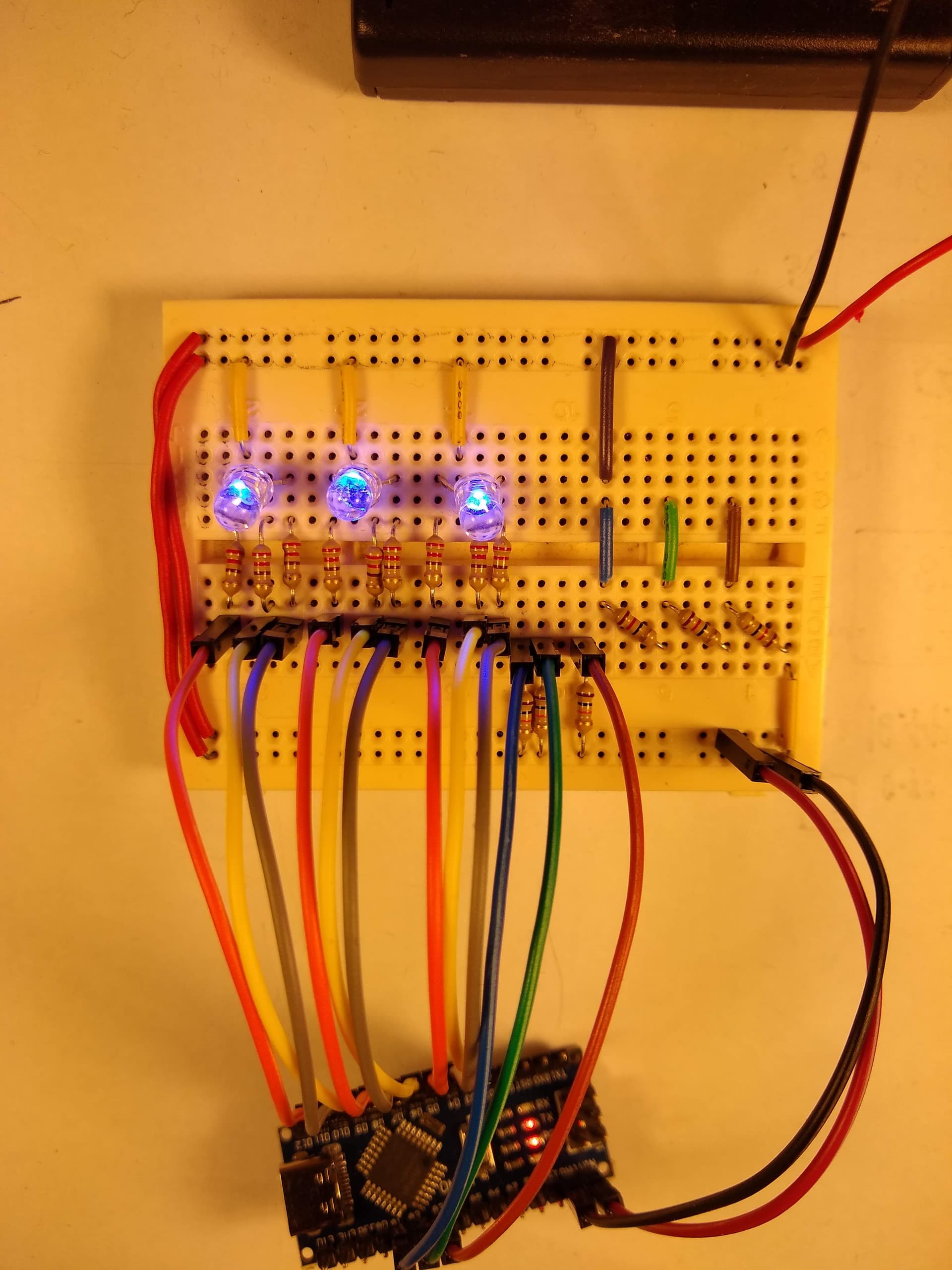
I have made a circuit that reads ADC from a potential divider. So, <16%, >16% & <50%, >50% & <82%, and >82% have different outputs.
One of them (A3) is bad, good, good on battery power, when i want bad, bad, good. Essentially the outputs are not responding as required according to the analogue input. When I power them off USB they are bad, bad, bad! Can anyone suggest what is going wrong?
I have enclosed code, how can I show a picture if that helps?
// Pin Definitions
const int d3 = 3;
const int d4 = 4;
const int d5 = 5;
const int d6 = 6;
const int d7 = 7;
const int d8 = 8;
const int d9 = 9;
const int d10 = 10;
const int d11 = 11;
const int a1 = A1;
const int a2 = A2;
const int a3 = A3;

void setup() {
  // Initialize digital pins as outputs
  pinMode(d3, OUTPUT);
  pinMode(d4, OUTPUT);
  pinMode(d5, OUTPUT);
  pinMode(d6, OUTPUT);
  pinMode(d7, OUTPUT);
  pinMode(d8, OUTPUT);
  pinMode(d9, OUTPUT);
  pinMode(d10, OUTPUT);
  pinMode(d11, OUTPUT);

  // Set all outputs low initially
  digitalWrite(d3, LOW);
  digitalWrite(d4, LOW);
  digitalWrite(d5, LOW);
  digitalWrite(d6, LOW);
  digitalWrite(d7, LOW);
  digitalWrite(d8, LOW);
  digitalWrite(d9, LOW);
  digitalWrite(d10, LOW);
  digitalWrite(d11, LOW);

  delay(1000); // Pause for 1 second

  // Set d4, d7, and d10 high
  digitalWrite(d4, HIGH);
  digitalWrite(d7, HIGH);
  digitalWrite(d10, HIGH);
  delay(1000); // Pause for 1 second

  // Set all outputs low
  digitalWrite(d4, LOW);
  digitalWrite(d7, LOW);
  digitalWrite(d10, LOW);
}

void loop() {
  // Loop1 start - Repeat 3 times only
  for (int i = 0; i < 3; i++) {
    digitalWrite(d4, HIGH);
    delay(100); // Pause for 0.25 seconds
    digitalWrite(d4, LOW);
    digitalWrite(d7, HIGH);
    delay(100); // Pause for 0.25 seconds
    digitalWrite(d7, LOW);
    digitalWrite(d10, HIGH);
    delay(100); // Pause for 0.25 seconds
    digitalWrite(d10, LOW);
    delay(100); // Pause for 0.25 seconds
  }

  // After Loop1 runs 3 times, set d4, d7, and d10 high again
  digitalWrite(d4, HIGH);
  digitalWrite(d7, HIGH);
  digitalWrite(d10, HIGH);

  // Now begin Loop2, which runs indefinitely
  while(true) {
    int voltageA3 = analogRead(a3); // Read A3
    float voltageA3Percentage = (voltageA3 / 1023.0) * 100; // Convert to percentage

    // Check A3 voltage levels and adjust outputs accordingly
    if (voltageA3Percentage < 16) {
      digitalWrite(d5, LOW);
      digitalWrite(d3, LOW);
      digitalWrite(d4, HIGH);
    } else if (voltageA3Percentage >= 16 && voltageA3Percentage < 50) {
      digitalWrite(d4, LOW);
      digitalWrite(d5, LOW);
      digitalWrite(d3, HIGH);
    } else {
      digitalWrite(d3, LOW);
      digitalWrite(d4, LOW);
      digitalWrite(d5, HIGH);
    }

    int voltageA2 = analogRead(a2); // Read A2
    float voltageA2Percentage = (voltageA2 / 1023.0) * 100; // Convert to percentage

    // Check A2 voltage levels and adjust outputs accordingly
    if (voltageA2Percentage < 16) {
      digitalWrite(d6, LOW);
      digitalWrite(d8, LOW);
      digitalWrite(d7, HIGH);
    } else if (voltageA2Percentage >= 16 && voltageA2Percentage < 50) {
      digitalWrite(d6, LOW);
      digitalWrite(d7, LOW);
      digitalWrite(d8, HIGH);
    } else if (voltageA2Percentage >= 50 && voltageA2Percentage < 82) {
      digitalWrite(d7, LOW);
      digitalWrite(d8, LOW);
      digitalWrite(d6, HIGH);
    } else {
      digitalWrite(d7, LOW);
      digitalWrite(d6, LOW);
      digitalWrite(d8, HIGH);
    }

    int voltageA1 = analogRead(a1); // Read A1
    float voltageA1Percentage = (voltageA1 / 1023.0) * 100; // Convert to percentage

    // Check A1 voltage levels and adjust outputs accordingly
    if (voltageA1Percentage < 16) {
      digitalWrite(d9, LOW);
      digitalWrite(d11, LOW);
      digitalWrite(d10, HIGH);
    } else if (voltageA1Percentage >= 16 && voltageA1Percentage < 90) {
      digitalWrite(d9, LOW);
      digitalWrite(d10, LOW);
      digitalWrite(d11, HIGH);
    } else {
      digitalWrite(d10, LOW);
      digitalWrite(d11, LOW);
      digitalWrite(d9, HIGH);
    }

    // Loop2 will continue running indefinitely
  }
}