Programing a spherical robot with math (based on 2 motorized gimbal rings)

Ok, so some backstory (You can skip to paragraph 4). I’ve been wanting to build a spherical robot for some time now, the problem of these robots is there price. From the Omni wheels to the 4 motors to the materials. It was simply too much for a 16yr old.
I also never really liked the idea of a hamster drive, it was unreliable and didn’t have the torque needed for navigating rough tertian. Id much rather have something directly connected to the sphere like a pendulum but didn’t like the fact that they couldn’t move like and omnidirectional hamster drive could. I was told by my peers that I wanted something that simply could not exist. But you cant stop innovation.
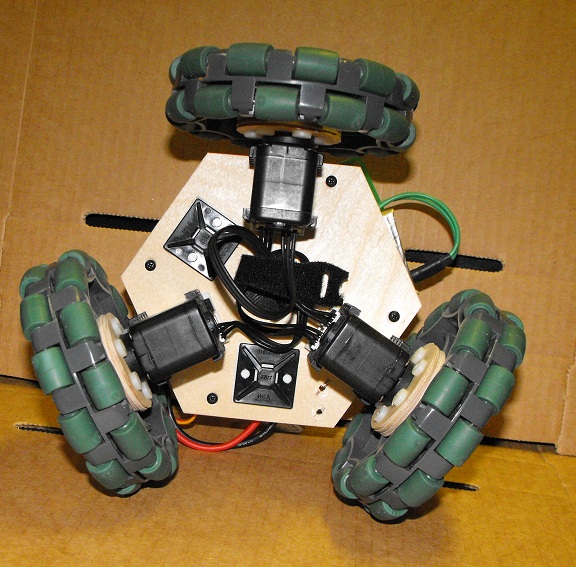
I believe that my design overcomes the issues and takes the best from both. This design is basically a heavy weight near the ground surrounded by a spherical gimbal which is plated with a vacuum formed PVC sphere.
So what’s the catch. Well the catch is that it requires an advanced function to calculate the needed ratio of steps by each motor (stepper motor that is) to move in any given direction based on the moving position of the second motor calculated by a rotary encoder on the first motor. It’s a mouthful, I know. But because the second motor is placed on the ring being rotated by the first, I need to change speeds depending on the direction desired to be traveled and the position of motor 2.
The equation will be used in conjunction with a compass which will first determine what direction it wants to go.

So lets say
The compass position is represented by a
The desired direction is represented by b
And the angel of the second motor motor is represented by c
I need to use this to find a ratio between the number of identical steps to be taken by each motor
(motor 1 (x), motor 2 (y))

I then need to use another equation or even the same equation to find how fast the motors need to travel to go at a one unit of speed so that I can keep the speeds constant and easily change speed. All this, I believe, can be calculated by an Arduino Nano if the equation is simplified enough.
I don’t even know where to start.

This sounds like a reasonably good senior year project for a college degree in mechanical engineering.

It is not too far removed from this elegant design using reaction wheels.

Here's the image attached to the top post.

How to insert uploaded images.

I'm trying to figure out how you want the motors to interact with the outside world.

Can the blue ring rotate in a way which would allow us to see the ring as a circle rather than a bar?

Would it be possible for the robot to roll toward the viewer (out from the screen)?

If this sort of movement were possible, I see all sorts of navigation problems for the robot.

What happens when the red ring's rotation axis is aligned with the up and down axis of the robot? The robot would no longer be able to move in any direction.

I'd think you'd have all sorts of "gimbal lock" type problems is you used this control mechanism.

I think omni wheels would be a much easier solution. You don't need four motors and wheel for an omni wheeled robot. Three wheels work great.

I used three of Vex's 4" wheels(Vex makes lots of cool omni wheels). The math behind omni wheels isn't too hard.

Here's the equation relating wheel speed with robot speed.

SpeedOfWheel = SpeedOfRobot * cos(angleOfWheelFromDirectionOfTravel)

I have heck of a time convincing people but an omni wheeled robot can travel faster than a conventional wheeled robot with the same size of wheels using the same max rpm of the motors.

Here's a video I made in an attempt to explain the relationship between the wheel rotation speed with the robot's speed.

I used Dynamixel AX-12+ servos/motors with my three wheeled omni bot. There are lots of less expensive options. I think a good metal gear CR servo like HobbyKing's HXT12K could be used to power the robot.

Here's my "spin straight" video, showing the robot spinning while moving in (hopefully) a straight line.

Having an omni wheeled robot travel in a figure 8 is surprisingly easy. Just keeping incrementing the direction of travel until a full circle has been made and then do the same thing with the direction of travel changing in the opposite direction.

Another omni directional wheel option is the Mecanum wheel. Mecanum wheels might too cool to enclose in a ball.

Dagu's Rover 5 is a pretty reasonably priced way to getting four motors with quadrature encoders. Encoder feedback is very important component of the Mecanum wheel control algorithm. I thought the robot was very hard to control before I added the encoder feedback component.

Here's a video showing the robot in action (make sure and skip the first two minutes).

Here's a link to a pdf explaining the equations used in the control algorithm. I'm not convinced the pdf is correct. I had to modify the equations a bit (change the sign on some components) to get the motors to move the right direction.

The Vex Mecanum wheels and the Dagu Rover 5 each cost about $60. I'm using two L298N h-bridge PCBs I purchased off ebay for about $3 each to power the motors. The L298N drops too much voltage to power the robot from a 2S LiPo so I'm powering with a 3S LiPo. I've been using this robot for about four years and it still works great. It's a lot of fun to see people's reaction the first time they see the robot moving sideways.

With both omni wheels and Mecanum wheels, the control algorithms aren't too hard. The equations just involve a bit of trig.

If I understand your diagram correctly, I don't think your system offers an advantage over using omni directional robot wheels. If I understand your diagram correctly, I think the control mechanism will have severe limitation because of problems caused by gimbal lock.

One advantage to using omni directional wheels is you should be able to use the control mechanism independently from the ball housing.

Stop cross-posting. Other thread removed.

STOP CROSS-POSTING. OTHER THREAD REMOVED.

You bring up some good pointy Duen. The motor axis of the omniwheels is parelell to the balls outside. The center is a globe and weight which rotates the second axis which is a ring around the glide. Opposite to the globes rotational axis is the second axis. In worst casenerio I can use this mechanism as a pendulum drive.
Omni wheeled hamster drives are cool, however they require disconnected motors from the shell. For my ablications this is a waste of torque, I will be using this over rougth terrain to navigate harsh environments. This levels me with the popular pendulum drive or this concept which can also work as a cheaper pendulum drive. A hamster would have very little torque.
As far as the second ring coming to a right angel with the ground. I would know due to the rotary encoders. And since the first axis is always parelell to the grould I could simply rotate the second