I'm using a Linkit ONE, i have deleted almost all my code back to the basics but still no luck.
I will post code in 2 posts as it to much for 1 post.
#include <LEEPROM.h> // Needed to write to EEPROM storage

boolean programMode = false; // Initialize program mode to false
boolean match = false; // initialize card match to false
byte storedCard[6]; // Stores an ID read from EEPROM
byte readCard[6]; // Sotres an ID read from the RFID reader
byte checksum = 10; // Stores the checksum to verify the ID
#define failPin 3 // Red LED
#define passPin 4 // Grenn LED
#define relay 2 // door relay
#define MAX_NO_CARDS 20

void setup()
{
  Serial1.begin(9600); // RFID
  pinMode(passPin, OUTPUT); // Connected to Green on tri-color LED to indicate user is valid
  pinMode(failPin, OUTPUT); // Connected to Red on tri-color LED to indicate user is NOT valid or read failed
  pinMode(relay, OUTPUT);
  delay(3000);
}

void loop()
{


  byte val = 0; // Temp variable to hold the current byte
  if (Serial1.available() > 0) // If the serial port is available and sending data...
  {
    if ((val = Serial1.read()) == 2) // First Byte should be 2, STX byte
    {
      getID(); // Get the ID, sets readCard = to the read ID
      byte bytesread = 0;

      if ( findID(readCard) ) // If not, see if the card is in the EEPROM
      {

        digitalWrite(relay, HIGH);   // turn the LED on (HIGH is the voltage level)
        digitalWrite(passPin, HIGH);   // turn the LED on (HIGH is the voltage level)
        digitalWrite(failPin, HIGH);   // turn the LED on (HIGH is the voltage level)
        delay(500);              // wait for a second
        digitalWrite(relay, LOW);    // turn the LED off by making the voltage LOW
        digitalWrite(passPin, LOW);    // turn the LED off by making the voltage LOW
        digitalWrite(failPin, LOW);    // turn the LED off by making the voltage LOW
      }
      else
      {

        digitalWrite(passPin, HIGH);   // turn the LED on (HIGH is the voltage level)
        digitalWrite(failPin, HIGH);   // turn the LED on (HIGH is the voltage level)
        delay(500);              // wait for a second
        digitalWrite(passPin, LOW);    // turn the LED off by making the voltage LOW
        digitalWrite(failPin, LOW);    // turn the LED off by making the voltage LOW

      }

    }
  }
  delay(200);

}

void getID()
{
  byte bytesread = 0;
  byte i = 0;
  byte val = 0;
  byte tempbyte = 0;
  // 5 HEX Byte code is actually 10 ASCII Bytes.
  while ( bytesread < 12 ) // Read 10 digit code + 2 digit checksum
  {
    if ( Serial1.available() > 0) // Check to make sure data is coming on the serial line
    {
      val = Serial1.read(); // Store the current ASCII byte in val
      if ((val == 0x0D) || (val == 0x0A) || (val == 0x03) || (val == 0x02))
      { // If header or stop bytes before the 10 digit reading
        break; // Stop reading
      }
      if ( (val >= '0' ) && ( val <= '9' ) ) // Do Ascii/Hex conversion
      {
        val = val - '0';
      }
      else if ( ( val >= 'A' ) && ( val <= 'F' ) )
      {
        val = 10 + val - 'A';
      }
      if ( bytesread & 1 == 1 ) // Every two ASCII charactors = 1 BYTE in HEX format
      {
        // Make some space for this hex-digit by
        // shifting the previous hex-digit with 4 bits to the left:
        readCard[bytesread >> 1] = (val | (tempbyte << 4));
        if ( bytesread >> 1 != 5 ) // If we're at the checksum byte,
        {
          checksum ^= readCard[bytesread >> 1]; // Calculate the checksum using XOR
        };
      }
      else // If it is the first HEX charactor
      {
        tempbyte = val; // Store the HEX in a temp variable
      };
      bytesread++; // Increment the counter to keep track
    }
  }
  bytesread = 0;
}

int findIDSLOT( byte find[] )
{
  int count = EEPROM.read(0); // Read the first Byte of EEPROM that
  // Serial.print("Count: "); // stores the number of ID's in EEPROM
  // Serial.print(count);
  //Serial.print("n");
  for ( int i = 1; i <= count; i++ ) // Loop once for each EEPROM entry
  {
    readID(i); // Read an ID from EEPROM, it is stored in storedCard[6]
    if ( checkTwo( find, storedCard ) ) // Check to see if the storedCard read from EEPROM
    { // is the same as the find[] ID card passed
      //Serial.print("We have a matched card!!! n");
      return i; // The slot number of the card
      break; // Stop looking we found it
    }
  }
}


}
boolean checkTwo ( byte a[], byte b[] )
{
  if ( a[0] != NULL ) // Make sure there is something in the array first
    match = true; // Assume they match at first
  for ( int k = 0; k < 5; k++ ) // Loop 5 times
  {
    /*
    Serial.print("[");
    Serial.print(k);
    Serial.print("] ReadCard [");
    Serial.print(a[k], HEX);
    Serial.print("] StoredCard [");
    Serial.print(b[k], HEX);
    Serial.print("] n");
    */
    if ( a[k] != b[k] ) // IF a != b then set match = false, one fails, all fail
      match = false;
  }
  if ( match ) // Check to see if if match is still true
  {
    //Serial.print("Strings Match! n");
    return true; // Return true
  }
  else {
    //Serial.print("Strings do not match n");
    return false; // Return false
  }
}

boolean findID( byte find[] )
{
  int count = EEPROM.read(0); // Read the first Byte of EEPROM that
  // Serial.print("Count: "); // stores the number of ID's in EEPROM
  // Serial.print(count);
  //Serial.print("n");
  for ( int i = 1; i <= count; i++ ) // Loop once for each EEPROM entry
  {
    readID(i); // Read an ID from EEPROM, it is stored in storedCard[6]
    if ( checkTwo( find, storedCard ) ) // Check to see if the storedCard read from EEPROM
    { // is the same as the find[] ID card passed
      //Serial.print("We have a matched card!!! n");
      return true;
      break; // Stop looking we found it
    }
    else // If not, return false
    {
      //Serial.print("No Match here.... n");
    }
  }
  return false;
}

void openDoor( int setDelay )
{
}

void readID( int number ) // Number = position in EEPROM to get the 5 Bytes from
{
  int start = (number * 5 ) - 4; // Figure out starting position
  //Serial.print("Start: ");
  //Serial.print(start);
  //Serial.print("nn");
  for ( int i = 0; i < 5; i++ ) // Loop 5 times to get the 5 Bytes
  {
    storedCard[i] = EEPROM.read(start + i); // Assign values read from EEPROM to array
    /*
    Serial.print("Read [");
    Serial.print(start+i);
    Serial.print("] [");
    Serial.print(storedCard[i], HEX);
    Serial.print("] n");
    */
  }
}

void writeID( byte a[] )
{
  if ( !findID( a ) ) // Before we write to the EEPROM, check to see if we have seen this card before!
  {
    int num = EEPROM.read(0); // Get the numer of used spaces, position 0 stores the number of ID cards
    /*
    Serial.print("Num: ");
    Serial.print(num);
    Serial.print(" n");
    */
    int start = ( num * 5 ) + 1; // Figure out where the next slot starts
    num++; // Increment the counter by one
    EEPROM.write( 0, num ); // Write the new count to the counter
    for ( int j = 0; j < 5; j++ ) // Loop 5 times
    {
      EEPROM.write( start + j, a[j] ); // Write the array values to EEPROM in the right position
      /*
      Serial.print("W[");
      Serial.print(start+j);
      Serial.print("] Value [");
      Serial.print(a[j], HEX);
      Serial.print("] n");
      */
    }
    //successWrite();
  }
  else
  {
    //failedWrite();
  }
}

void deleteID( byte a[] )
{
  if ( !findID( a ) ) // Before we delete from the EEPROM, check to see if we have this card!
  {
    //failedWrite(); // If not
  }
  else
  {
    int num = EEPROM.read(0); // Get the numer of used spaces, position 0 stores the number of ID cards
    int slot; // Figure out the slot number of the card
    int start;// = ( num * 5 ) + 1; // Figure out where the next slot starts
    int looping; // The number of times the loop repeats
    int j;
    int count = EEPROM.read(0); // Read the first Byte of EEPROM that
    // Serial.print("Count: "); // stores the number of ID's in EEPROM
    // Serial.print(count);
    //Serial.print("n");
    slot = findIDSLOT( a ); //Figure out the slot number of the card to delete
    start = (slot * 5) - 4;
    looping = ((num - slot) * 5);
    num--; // Decrement the counter by one
    EEPROM.write( 0, num ); // Write the new count to the counter
    for ( j = 0; j < looping; j++ ) // Loop the card shift times
    {
      EEPROM.write( start + j, EEPROM.read(start + 5 + j)); // Shift the array values to 5 places earlier in the EEPROM
      /*
      Serial.print("W[");
      Serial.print(start+j);
      Serial.print("] Value [");
      Serial.print(a[j], HEX);
      Serial.print("] n");
      */
    }
    for ( int k = 0; k < 5; k++ ) //Shifting loop
    {
      EEPROM.write( start + j + k, 0);
    }
    //successDelete();
  }
}

void blinker () {
  digitalWrite(failPin, HIGH);   // turn the LED on (HIGH is the voltage level)
  delay(50);              // wait for a second
  digitalWrite(failPin, LOW);    // turn the LED off by making the voltage LOW
}

void blinkerBlue () {
  digitalWrite(passPin, HIGH);   // turn the LED on (HIGH is the voltage level)
  delay(50);              // wait for a second
  digitalWrite(passPin, LOW);    // turn the LED off by making the voltage LOW
I have tried the USB portable battery to try and power up via the USB port, it powers up ok but dose not run correctly as described above. I then tried 3AA battery pack, i then tried 4AA in the regular DC input.
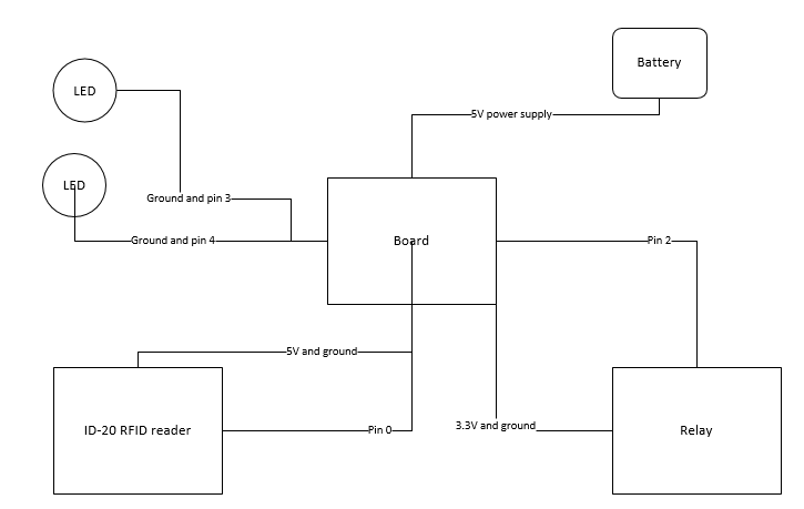
Can you please post a complete copy of your circuit, in CAD or a picture of a hand drawn circuit in jpg, png or pdf?
This means including you power supplies.
Hi,
Sorry a circuit diagram, showing individual wires, a picture too would help.
Have you got current limit resistors in series with each of your LEDs?
Have you checked on the current required to fire one of those RFID units.
Do you have a DMM?
Maximum voltage applied to Pin 2 (Vcc) 5.5volt
Maximum voltage applied to Pin 2 (Reset) Vcc + 0.7v, -0.7v
Maximum current drawn from Pin 3 ( Antenna) +/- 75mA
Maximum 125 KHz RF Voltage at Pin 4 (Antenna) +/- 80volt Peak
Maximum current drawn from Pin 5 (Card Present) +/- 5mA
Maximum current drawn from Pin 6 (Tag in Range) +/- 5mA
Maximum Voltage at Pin 7 (Format Selector) Vcc + 0.7v, -0.7v
Maximum current drawn from Pin 8 (Data1) +/- 5mA
Maximum current drawn from Pin 9 (Data0) +/- 5mA
Maximum current drawn from Pin 10 (Beeper) +/- 10mA
Additionally, Pins 5, 6, 7, 8, 9 & 10 may not have a voltage exceeding Vcc + 0.7v, -0.7v
It seems to me that if the project works as intended while connected to computer via USB that any sort of programming error can be ruled out.
Seeing as how the USB port is providing 5V, and your project drawing indicates use of 3.3V one could also safely assume that a voltage regulator is in place, it would further make sense (but would need to be actually verified on the board) that the connector for battery input uses the same voltage regulation circuit as does the USB connection, because why would there need to be separate circuits to handle the same job.
I feel the most likely culprit here is back EMP produced when the relay is deactivated. The collapsing magnetic field induces reverse voltage back into the power lines unless some form of protection is used (a diode). I am thinking that the computer manufacture anticipated that at some point a device may induce unwanted voltage on the USB power lines and took steps to protect the port (once again a diode). I have not actually tested such a thing with my computer, but I do know from experience that if I cause a short in the 5V lines the computer will deactivate the port until it the next reboot.
Without this protection (when you are using battery connector or a USB battery pack) when the relay deactivates it is likely producing a reverse voltage spike on the power lines that either causes a reset or creates enough of a brown out to cause program execution to halt.
If you do not have a diode in place on your relay it may be worth looking in to, simply Google "relay back emf" and I think you should find the information you need to implement this.
When i scan the both LED's light which tells me the reader has picked up a card, this does not happen when powered with batteries but works flawlessly when plugged into the USB.
BH72:
It seems to me that if the project works as intended while connected to computer via USB that any sort of programming error can be ruled out.
Seeing as how the USB port is providing 5V, and your project drawing indicates use of 3.3V one could also safely assume that a voltage regulator is in place, it would further make sense (but would need to be actually verified on the board) that the connector for battery input uses the same voltage regulation circuit as does the USB connection, because why would there need to be separate circuits to handle the same job.
I feel the most likely culprit here is back EMP produced when the relay is deactivated. The collapsing magnetic field induces reverse voltage back into the power lines unless some form of protection is used (a diode). I am thinking that the computer manufacture anticipated that at some point a device may induce unwanted voltage on the USB power lines and took steps to protect the port (once again a diode). I have not actually tested such a thing with my computer, but I do know from experience that if I cause a short in the 5V lines the computer will deactivate the port until it the next reboot.
Without this protection (when you are using battery connector or a USB battery pack) when the relay deactivates it is likely producing a reverse voltage spike on the power lines that either causes a reset or creates enough of a brown out to cause program execution to halt.
If you do not have a diode in place on your relay it may be worth looking in to, simply Google "relay back emf" and I think you should find the information you need to implement this.
Thanks for the info, what i will do is remove the relay to see if this solves the problem.