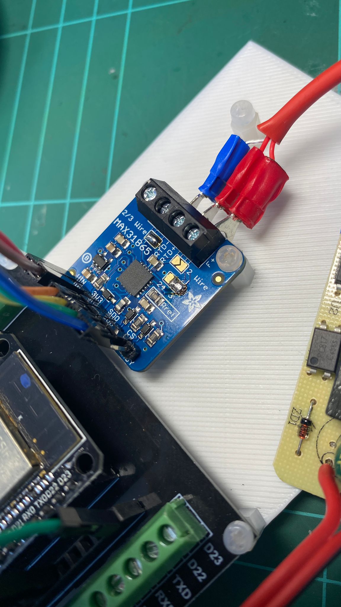
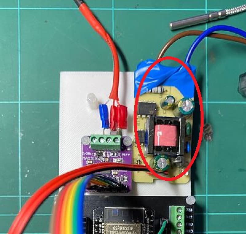
Hi, I am having the same issue with the RTD.
#include <Wire.h>
#include <LiquidCrystal_I2C.h>
#include <Adafruit_MAX31865.h>
#include <PID_v1.h>
// Pin Definitions
#define RELAY_PIN 7
// RTD Sensor (PT100) - MAX31865 Setup
#define MAX31865_CS_PIN 10
Adafruit_MAX31865 thermo = Adafruit_MAX31865(MAX31865_CS_PIN, 11, 12, 13); // CS, DI, DO, CLK
// PID Variables
double setPoint = 60.0;
double inputTemp, outputTemp;
double Kp = 2.0, Ki = 0.0, Kd = 0.0;
PID myPID(&inputTemp, &outputTemp, &setPoint, Kp, Ki, Kd, DIRECT);
// LCD Display Setup (I2C)
LiquidCrystal_I2C lcd(0x27, 16, 2);
void setup() {
Serial.begin(9600);
pinMode(RELAY_PIN, OUTPUT);
digitalWrite(RELAY_PIN, LOW);
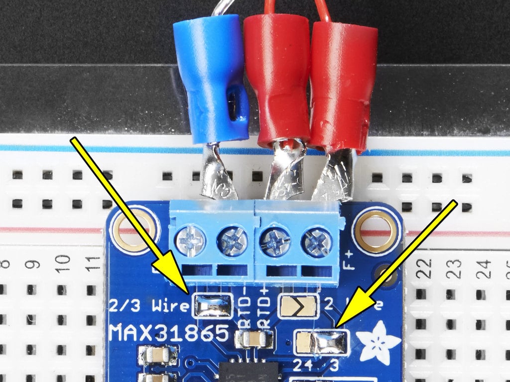
thermo.begin(MAX31865_3WIRE);
myPID.SetMode(AUTOMATIC);
myPID.SetOutputLimits(0, 255);
lcd.init();
lcd.backlight();
displayMessage("PID Control", "Initializing...");
delay(2000);
lcd.clear();
}
void loop() {
uint16_t rtd = thermo.readRTD();
Serial.print("Raw RTD: "); // Add this line
Serial.println(rtd); // Add this line
inputTemp = thermo.temperature(rtd, MAX31865_3WIRE);
printSerialData(inputTemp); // Just print the temperature
myPID.Compute();
controlHeatingElement(outputTemp);
displayTemperature();
delay(1000);
}
void printSerialData(double temp) {
Serial.print("Temperature: ");
Serial.println(temp);
Serial.print("PID Output: ");
Serial.println(outputTemp);
}
void controlHeatingElement(double output) {
analogWrite(RELAY_PIN, output); // PWM Control
}
void displayTemperature() {
lcd.clear();
lcd.setCursor(0, 0);
lcd.print("Set: ");
lcd.print(setPoint);
lcd.print("C");
lcd.setCursor(0, 1);
lcd.print("Temp: ");
lcd.print(inputTemp);
lcd.print("C");
}
void displayMessage(const char *line1, const char *line2) {
lcd.clear();
lcd.setCursor(0, 0);
lcd.print(line1);
lcd.setCursor(0, 1);
lcd.print(line2);
}
These are the results in my serial monitor.
Temperature: -242.01
PID Output: 255.00
Raw RTD: 7778
#include "Adafruit_MAX31865.h"

Adafruit_MAX31865 thermo = Adafruit_MAX31865(10, 11, 12, 13);

#define RREF 430.0
#define RNOMINAL 100.0

void setup() {
  Serial.begin(9600);
  thermo.begin(MAX31865_3WIRE);  // 2WIRE, 3WIRE, 4WIRE
}

void loop() {
  uint8_t fault = thermo.readFault();
  if (fault) {
    Serial.print("Fault 0x");
    Serial.println(fault, HEX);
    thermo.clearFault();
  } else {
    float temp = thermo.temperature(RNOMINAL, RREF);
    Serial.print("Temp:");
    Serial.println(temp);
  }


}
When I plug in the code above, my results show ~5.5C inside an ice bath.

uint16_t rtd = thermo.readRTD();
Serial.print("Raw RTD: ");  // Add this line
Serial.println(rtd);        // Add this line
inputTemp = thermo.temperature(rtd, MAX31865_3WIRE);
Seems like the OP's code also has the above code. Could that be causing the issue he is describing that I am also experiencing?