Hello. I'm new to arduino programming, need help to understand.
Can someone help me build arduino code , at start, pump is on for 5 minute, but If no water flow for 5 minute while pump is on, then pump should off. then turn on later after 5 minute while then check the flow rate again. loop thank's
You can start learning by working with the test code named: Blinking without delay.
Do You know how to interface the pump to the controller?
1 Like
Step 1: Learn how to turn the pump on and off
Step 2: Learn how to turn the pump on for 5 minutes, then off
Step 3: Learn how to interface to flow sensor.
Step 4: Put it all together.
1 Like
Nope. We can help you with code you have attempted.
yes,. with relay of course. I'm newbie in this program code, and really don't know how to make delay of relay instead main loop.
I just start learning by copy and paste the code instead learn word by word function. sorry
Relay on for 5 minute. then check flow rate. if there any flow then relay still on. if not then relay off for 5 minute.
i think this is my problem Arduino - Multitask Your Programs - Example with 2 LEDs Blinking at Different Rates - YouTube thank all for helping.
Hello fachromiez
Before start with coding study tihe IPO model and design a program structure using functions.
All functions can be tested separtly and after testing glue together for the project.
Have a nice day and enjoy coding in C++.
i don't speak english well. that's why i can't explain it better. sorry. i know how logic is this. just need more knowledge.
i build some system that can measure water tank level with ultrasonic and monitor water flow from 2 pump (in, out), 1 pump to fill in the tank, but must have to check weather is there water flow on pipe or not. then if no water flow in pipe then pump goes OFF after 5 minute then delay 5 minutes later pump should ON again still check the flow loop again, the second out pump only ON when tank level above 50%. if not pump 2 will OFF. all the 3 sensor and 2 relay display their activity on 2004 i2c LCD. water in liter/ minute, level tank in percent then relay in symbols.
Hello fachromiez
Post your sketch, well formated, with comments and in so called code tags "</>" and schematic to see how we can help.
Have a nice day and enjoy coding in C++.
1 Like
#include "LiquidCrystal.h"
//Tank leve;
#define trigPin 8
#define echoPin 9
// Define variables:
long duration;
int TankLevel;
int TankLevelPercentage;
//Tank leve;

//Flo sens out pompa dorong
const int watermeterPin = 2; //Flo
volatile int  pulse_frequency;
unsigned int  literperm;
unsigned long currentTime, loopTime;
byte sensorInterrupt = 0;  // 0 = pin 2; 1 = pin 3
//Flo sens out

//Flo sens in pompa hisap
const int watermeterPinIn = 3; //Flo
volatile int  pulse_frequencyIn;
unsigned int  literpermIn;
unsigned long currentTimeIn, loopTimeIn;
byte sensorInterruptIn = 1;  // 0 = pin 2; 1 = pin 3
//Flo sens in


//LCD L2C
#include <LiquidCrystal_I2C.h>
// set the LCD number of columns and rows
int lcdColumns = 20;
int lcdRows = 4;
// set LCD address, number of columns and rows
// if you don't know your display address, run an I2C scanner sketch
LiquidCrystal_I2C lcd(0x27, lcdColumns, lcdRows);// SCL to pin A5. SDA ti pin A4)
char line0[21];
char line1[21];
//LCD L2C

//Relay pump
byte Relay1   = 12; //Relay1 pompa dorong
byte Relay2   = 13; //Relay2 pompa tarik
//Relay pump

void getFlow ()
{
  pulse_frequency++;
  pulse_frequencyIn++;
}


void setup() {
  Serial.begin(9600);// Begin Serial communication at a baudrate of 9600:

  lcd.init();

  pinMode(watermeterPin, INPUT); //Flo sens out
  pinMode(watermeterPinIn, INPUT); //Flo sens in
  attachInterrupt(sensorInterrupt, getFlow, FALLING); //Flo sens out
  attachInterrupt(sensorInterruptIn, getFlow, FALLING); //Flo sens in
  currentTime = millis(); //Flo sens out
  currentTimeIn = millis(); //Flo sens in
  loopTime = currentTime; //Flo sens out
  loopTimeIn = currentTimeIn; //Flo sens in

  //

  //Tank leve;
  // Define inputs and outputs
  pinMode(trigPin, OUTPUT);
  pinMode(echoPin, INPUT);
  //Tank leve;

  //Relay pump
  pinMode(Relay1, OUTPUT);
  pinMode(Relay2, OUTPUT);
  //Relay pump
}

void flowROut() {
  currentTime = millis();
  if (currentTime >= (loopTime + 1000))
  {
    loopTime = currentTime;
    literperm = (pulse_frequency / 12);
    pulse_frequency = (float)0;
  }
  else if (literperm >= 1) {
    lcd.backlight();
  }
  else
    lcd.noBacklight();
}

void flowRIn() {
  currentTimeIn = millis();
  if (currentTimeIn >= (loopTimeIn + 1000))
  {
    loopTimeIn = currentTimeIn;
    literpermIn = (pulse_frequencyIn / 12);
    pulse_frequencyIn = (float)0;
  }
  else if (literpermIn >= 1) {
    lcd.backlight();
  }
  else
    lcd.noBacklight();
}

void chkflow() {
  digitalWrite(Relay2, HIGH);

}


void Pump() {
  if ( TankLevelPercentage <= 10) {
    digitalWrite(Relay2, HIGH);
    lcd.setCursor(15, 1);
    lcd.print(">");
    digitalWrite(Relay1, LOW);
    lcd.setCursor(14, 1);
    lcd.print(" ");
    lcd.backlight();
  }
  else if (TankLevelPercentage >= 100) {
    digitalWrite(Relay2, LOW);
    lcd.noBacklight();
    lcd.setCursor(15, 1);
    lcd.print(" ");
  }
  else if (TankLevelPercentage >= 11) {
    digitalWrite(Relay1, HIGH);
    lcd.setCursor(14, 1);
    lcd.print("<");
    //lcd.backlight();
  }


  // else literperm = 0;
}

void TanklLvl() {

  // Clear the trigPin by setting it LOW:
  digitalWrite(trigPin, LOW);
  delayMicroseconds(5);
  // Trigger the sensor by setting the trigPin high for 10 microseconds:
  digitalWrite(trigPin, HIGH);
  delayMicroseconds(10);
  digitalWrite(trigPin, LOW);
  // Read the echoPin. pulseIn() returns the duration (length of the pulse) in microseconds:
  duration = pulseIn(echoPin, HIGH);
  // Calculate the TankLevel:
  TankLevel = duration * 0.0343 / 2 - 11;

  TankLevelPercentage = 110 - TankLevel * 100 / 90;
  // TankLevel = TankLevel * 100;
}


void loop() {

  TanklLvl();
  flowROut();
  flowRIn();
  Pump();

  lcd.display();
  lcd.setCursor(0, 0);
  lcd.print("Isi Tank: ");
  lcd.setCursor(10, 0);
  lcd.print(TankLevelPercentage);
  lcd.print("   ");

  lcd.setCursor(13, 0);
  lcd.print(" % ");

  lcd.setCursor(0, 1);
  lcd.print("Kran : ");
  lcd.setCursor(7, 1);
  lcd.print(literperm);
  lcd.print("  ");
  lcd.setCursor(10, 1);
  lcd.print("L/M");


  Serial.print("Isi Tank : ");
  Serial.print(TankLevelPercentage);
  Serial.print(" % ");
  Serial.print("Liter/M : ");
  Serial.println(literperm);
  //lcd.noBacklight();
  delay(100);

}```

may i correct, just learnd from copy paste.i need to put some logic for Relay1
where Relay1 start for 5 minute if there any pulse from watermeterPinIn then Relay1 still ON, but when no pulse from watermeterPinIn after 5 minute Relay1 go OFF, then delay 5 minute. LOOP to start Relay1 ON again.. Without distrub main loop program.
Hi fachromiez,
if it is difficult for you to write in english then use google translate.
I'm really serious with this suggestion. Use google translate
Write everything in your native language and let do google-translate the translation.
The grammar won't be brilliant but the translation will be OK.
And the big advantage is that you can write all the important details in your native language.
best regards Stefan
1 Like
I don't have your hardware laying around, This means I can't copy your hardware-setup.
Write a description what is functioning and what not.
1 Like
What else do you have going on in your project?
Of course it will be easy to add the pomp automation to any loop function written in a non-blocking style.
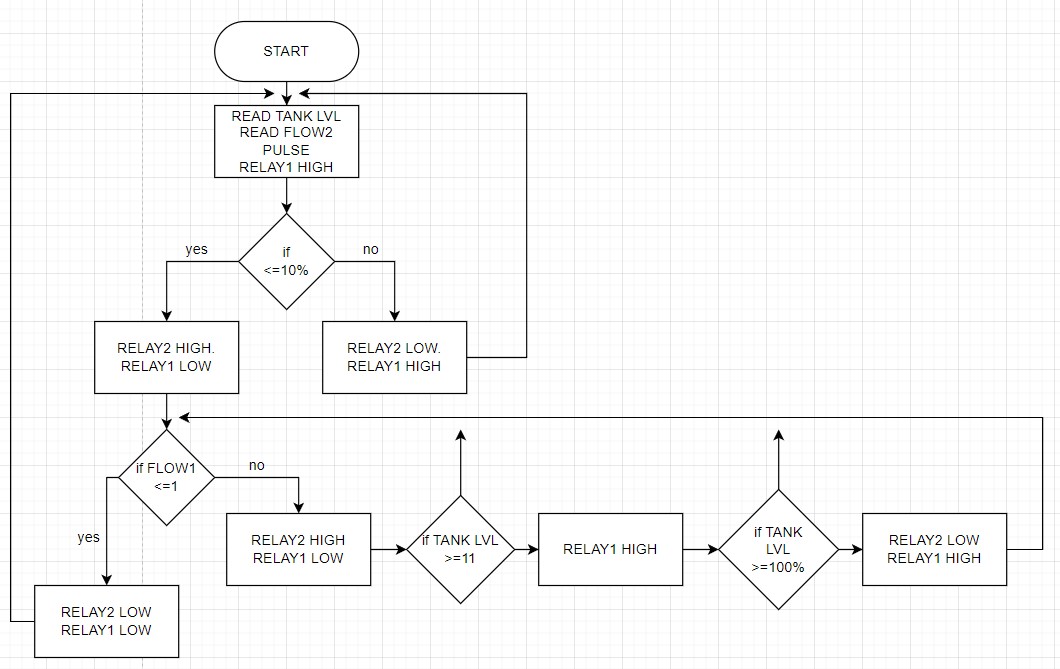
I suggest you draw a flowchart, no language problem there, just a good old fashioned flow chart for the pomp.
You description is vague or ambiguous or incomplete. This is what I get:
-
turn on the pomp from some signal.
-
pomp stays on as long as signal is present
-
pomp pomp shits off after five minutes with no signal
-
when the pomp turns off, ignore for five minutes any signal that woukd turn it on again
Is the signal continuous while there is flow? Or is it a pulse at some frequency and duty cycle that correlates to flow?
a7
Why is the interrupt routine shared between both flow sensors?
To give advice to this aspect:
If I understand right You a flowsensor for water thar flows in and a second for water that flows out of some kind of tank.
They have to count there pulses separately . This means you need two interrupt service routines.
a function
void getFlowOut ()
{
  pulse_frequency++;
}
and a second one
void getFlowIn ()
{
  pulse_frequencyIn++;
}
Each of them incrementing just their single variable
Both need to be assigned to their interrupt-pin
  attachInterrupt(digitalPinToInterrupt(sensorInterrupt), getFlowOut, FALLING)
  attachInterrupt(digitalPinToInterrupt(sensorInterruptIn), getFlowIn, FALLING)
the identifier sensorInterrupt is unprecise you should name it very clearly
const byte sensorInterruptOutflow_pin = 0;
const byte sensorInterruptInflow_pin = 1;
and then the attaching looks like this
  attachInterrupt(digitalPinToInterrupt(sensorInterruptOutflow_pin), getFlowOut, FALLING)
  attachInterrupt(digitalPinToInterrupt(sensorInterruptInflow_pin), getFlowIn, FALLING)
The digitalPinToInterrupt()-function assigns the correct interruptnumber automatically
best regards Stefan
1 Like
Nice, but absolutely no mention of any 5 minute lock on wait for signal to disappear, or 5 minute lock out after the pomp stops.
Add that to your diagram, very pretty so far…
Also, did you ever say what relay 1 and relay 2 do?
Could you please describe the flow sensor, post a link to it. Tell us how it is used to develop the signal you are reacting to.
if <= 10 %
Is that also referring to tank level?
a7
1 Like
If you enjoy taking time
to create a computergenerated plans of course you can do
For the communication-process it is enough to use quickly handdrawn plans
best regards Stefan
1 Like