I have a soundbar that goes into standbymode after 10 minutes (due to EU regulaltion). This is extremely annoying so I want to make a device that can press the powerbutton for me when I tell google assistant to do so.
The button is pressed when I make a ~800g pressure.
This is the first time I make someting like this. The only thing I've done before using arduino is a program that makes a ledstrip glow so I'm a real beginner.
Anyway, after some "googleing" I have figured out that I need this:
I don't understand what a "soundbar" does, excepy for sounding in some way.
When You indicate that You maybe intend to violate rules and regulations I hesitate to assist You.
"I have a soundbar that goes into standbymode after 10 minutes (due to EU regulaltion). This is extremely annoying so I want to make a device that can press the powerbutton for me when I tell google assistant to do so."
Maybe just put a toggle switch in parallel with the button. If you can get to the backside of the button, run two wires from its tabs to the outside and connect the wires to a NO relay.
Railroader:
I don't understand what a "soundbar" does, excepy for sounding in some way.
When You indicate that You maybe intend to violate rules and regulations I hesitate to assist You.
Hi,
I'm not intending to violate anything. Soundbar= external speaker.
For example if I paus a movie or show on my tv the soundbar detects that its inactive and goes into standy mode. If I come back after 15 minutes and press play again the sound is turned off and I have to go up again och press the powerbutton myself. To avoid this I though of this idé (just speak with google assistant and the assistant will press the button for me) plus its a fun project.
To sum it up
I stead of pressing the button myself arduino will press it for me on demand.
Get a NodeMC and a servo and some batteries to power the servo. Write a short program to make the servo move and see if it can push the switch. If not, try a bigger servo.
You an do the first tests by holding the servo in your hand but you will need to build the hardware to hold the servo in place where it can activate the switch.
Then, separately, write a short program that can interface with the web to get instructions (I have no experience of Google Assistant or Alexa - I would have anything like that in my home, I don't want the Mafia intruding on my privacy). This will probably be the more complex part of the program but there may well be online examples that you can copy.
When you can do the two parts separately it will be time to build the combined program.
Robin2
I dont think the google home part is hard at al. I have already set it up actially. All I need is a NodeMC so I can enter the connectrion (there are good code examples for that).
Yes I'm doing it in steps but I prefer to buy everything at once so I need to know if I'm buying the right stuff.
DrDiettrich
Very good info thanks again, I dont want to open it up since it feel more advanced and Im a beginner.
Do I really need a relay u think? Cant you turn it on or off by code without it? A relay can turn stuff on/off but cant the code do that on its own?
If you want to use a relay, look for the ESP01 relay modules. Doesn't get easier than that to build this project. Same MCU as used on the NodeMCU: the ESP8266.
For ease of programming, also get an ESP01 USB programming module.
mrgurgle:
Yes I'm doing it in steps but I prefer to buy everything at once.
In my experience that usually results in wrong parts taking up space in the "might be useful sometime" drawer.
Do I really need a relay u think? Cant you turn it on or off by code without it? A relay can turn stuff on/off but cant the code do that on its own?
The amount of current that an Arduino can control directly with its I/O pins is about 20mA at 5v. If you need to switch a bigger current or a higher voltage you need a relay or a transistor.
If you are going to use a servo to push a button you won't need a relay.
If you want to interface directly with the existing button switch contacts then a relay may the simplest because (within limits) it is indifferent to the voltage and current and the polarity in the contacts.
wvmarle:
If you want to use a relay, look for the ESP01 relay modules. Doesn't get easier than that to build this project. Same MCU as used on the NodeMCU: the ESP8266.
For ease of programming, also get an ESP01 USB programming module.
So if I get these two parts I don't need an arduino board since I could program it using arduino IDE and the ESP01 USB programming module?
Robin2:
In my experience that usually results in wrong parts taking up space in the "might be useful sometime" drawer.
I will follow that advice, thanks.
Robin2:
The amount of current that an Arduino can control directly with its I/O pins is about 20mA at 5v. If you need to switch a bigger current or a higher voltage you need a relay or a transistor.
If you are going to use a servo to push a button you won't need a relay.
If you want to interface directly with the existing button switch contacts then a relay may the simplest because (within limits) it is indifferent to the voltage and current and the polarity in the contacts.
...R
Oh now I think I understand how it works, so arduino has 5V current through the USB cable. Its possible to use 12V if you use an external power supply somehow and using the "Vin" pin instead of "5V" pin. But if I look at the datasheet for servo S90 (http://www.ee.ic.ac.uk/pcheung/teaching/DE1_EE/stores/sg90_datasheet.pdf) it says voltage 4.8-6 so I cant use 12Volts anyway. And there for I dont need an relay. Is that correct?
USB adapter like this one; there are several relay modules out there, I use this one. There are other relay modules out there. Check the manual on how to operate the relay.
mrgurgle:
Oh now I think I understand how it works, so arduino has 5V current through the USB cable. Its possible to use 12V if you use an external power supply somehow and using the "Vin" pin instead of "5V" pin.
I'm worried that you may still have things mixed up. However it is powered an Arduino works internally at 5v.
You are correct to say that you cannot power a relayservo with a 12v power supply. But that is not the reason why a relay is not needed.
Using a servo to push the button is one option.
Using a relay connected directly to the electrical contacts inside the switch is another option - but I have no idea whether it would be practical for you to get at the switch contacts to solder wires to them or whether it would work even if you could.
As you seem not to have a good understanding of electricity and electrical components I suggest you stick with the idea of using a relay to push the switch. There is much less to learn and much less that can go wrong.
...R
Edit to change "relay" to "servo" - apologies for the confusion
Robin2:
I'm worried that you may still have things mixed up. However it is powered an Arduino works internally at 5v.
You are correct to say that you cannot power a relay with a 12v power supply. But that is not the reason why a relay is not needed.
Tanks guys, I'll try to keep it as simple as possible until I have a better understanding of electricity. Therefore I'll start of by buying a servo and see if I can make it turn just with the arduino nano board. When that works I'll try the ESP01 relay module + USB module.
Robin2 What things do you think I have mixed up? Really want to learn.
Another thing. You said "You are correct to say that you cannot power a relay with a 12v power supply".
I did not get that part. What I meant was that you cannot power a servo (not relay) with a 12v power supply, because a relay can use 12v right if I'm not wrong?
Trying to study electricity now but its alot to take in and hard to know what I should focus on.
mrgurgle:
Robin2 What things do you think I have mixed up? Really want to learn.
I'm not sure - I am unclear what you had in mind when you wrote "Its possible to use 12V if you use an external power supply somehow and using the "Vin" pin instead of "5V" pin." Especially the piece in bold. Maybe if you post a photo of a simple pencil drawing showing how you were thinking of connecting things it would be clearer.
Another thing. You said "You are correct to say that you cannot power a relay with a 12v power supply".
Humble apologies - I should have said "servo" rather than "relay" - and in the circumstances I appreciate how that must have been very confusing. Apologies again. I have corrected my earlier Post.
Robin2:
I'm not sure - I am unclear what you had in mind when you wrote "Its possible to use 12V if you use an external power supply somehow and using the "Vin" pin instead of "5V" pin." Especially the piece in bold.
Just yesterday I watched a video by Adam Savage (the mythbuster) with one of his friends deploying an Arduino. They had a step-down supply outputting 5.2V, then I saw them connect it to the barrel jack of an Uno... That's the kind of guys that should know what they're doing!
In short, do not play with the "Vin" of the Nano or UNO or the "barrel jack" of the UNO. You require 5 V to operate these devices and the relay in particular, so you require a 5 V regulated power supply; USB "phone chargers" are presently the most economical and practical form.
The most practical WiFi device will probably be the WeMOS D1 Mini and a matching relay module. The NodeMCU is a different form factor and I do not recall a relay module that matches it. The vendor you cite is rather expensive, prices on eBay or Aliexpress are much lower albeit involve a postal delay. Programming the WeMOS D1 Mini is dead easy.
The ESP-01 combination with its relay board would be effective, but you also need the separate programming adaptor for the ESP-01 which is not as convenient as the WeMOS D1 Mini which can be programmed whilst assembled and is only marginally cheaper. While I use ESP-01s with this restriction, you really are better off with the D1 Mini.
wvmarle:
Just yesterday I watched a video by Adam Savage (the mythbuster) with one of his friends deploying an Arduino. They had a step-down supply outputting 5.2V, then I saw them connect it to the barrel jack of an UNO... That's the kind of guys that should know what they're doing!
So - maybe they are not as technically competent as they claim! Perhaps they have a few more "silent" backroom boys than they let on. Such is life.
wvmarle:
Just yesterday I watched a video by Adam Savage (the mythbuster) with one of his friends deploying an Arduino. They had a step-down supply outputting 5.2V, then I saw them connect it to the barrel jack of an Uno... That's the kind of guys that should know what they're doing!
Not if your description is correct.
The input to the barrel jack should be in the range 7-12v and the extremes are 6-20v (see the product tech specs)
Robin2:
I'm not sure - I am unclear what you had in mind when you wrote "Its possible to use 12V if you use an external power supply somehow and using the "Vin" pin instead of "5V" pin." Especially the piece in bold. Maybe if you post a photo of a simple pencil drawing showing how you were thinking of connecting things it would be clearer.
Humble apologies - I should have said "servo" rather than "relay" - and in the circumstances I appreciate how that must have been very confusing. Apologies again. I have corrected my earlier Post.
...R
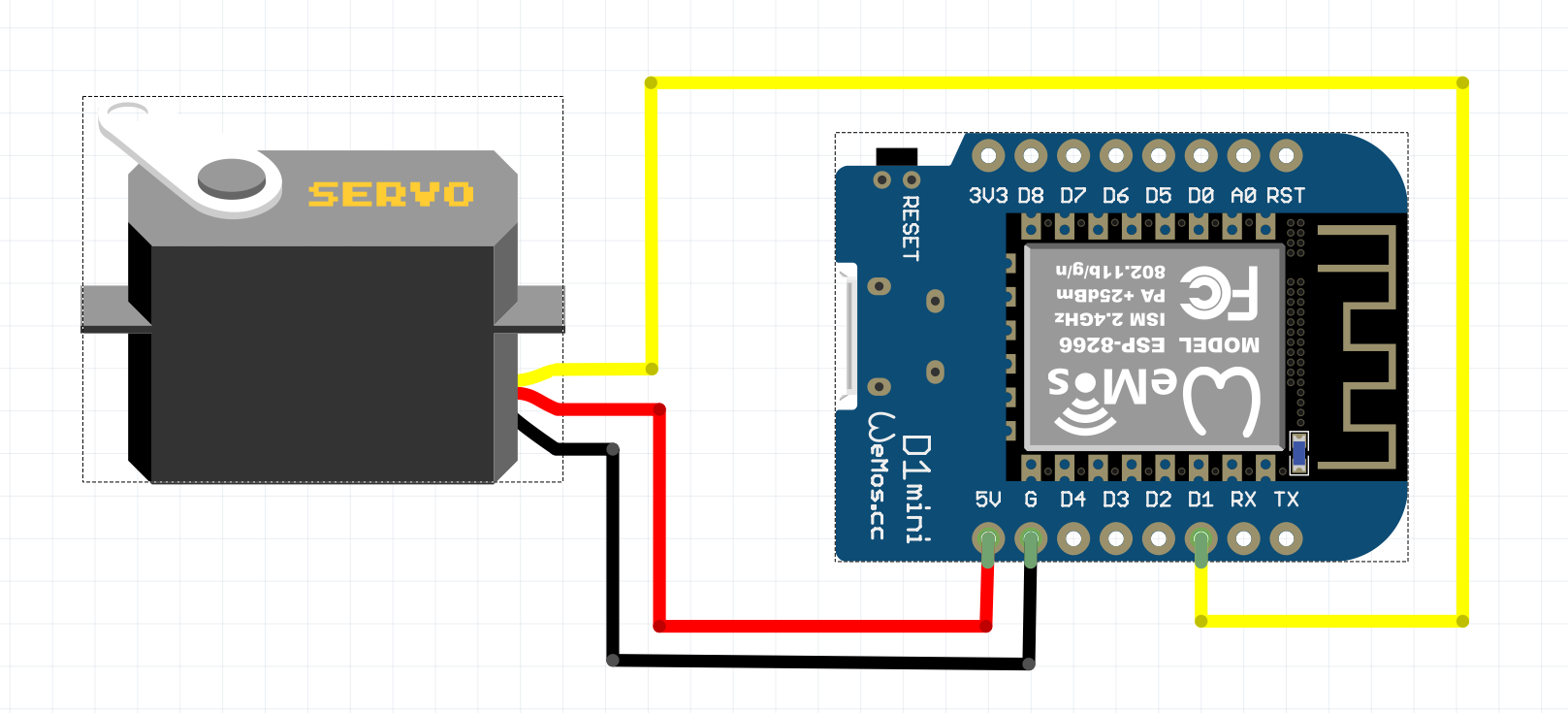
Thanks for the clarification and thanks for all the help. I may forgot to say that I initially was thinking of using my arduino nano since I already have one. On the nano board there are a pin called "VIN". Thats what I was talking about yearlier. I tought that it maybe is possible to connect a 12V battery to VIN and then have 12V instead of 5V. Isn't that correct? I understand that I dont need this for this project now though. This was my first sketch that I was thinking about. (No clue if its would had worked though). Now I think I will go with the Wemos D1 V3 instead.
You can power the nano by connecting 12v to the Vin pin. But that is not going to provide the 5v for your servos because, no matter where the Arduino power comes from, you should NOT draw power for a servo or any motor from the Arduino 5v pin. Motors and servos need their own power supply. Make sure that the servo GND is connected to the Arduino GND.
If you provide a regulated 5v supply for your servos you can also power the Arduino from that through its 5v pin - but, again, the power for the servos must NOT flow through the Arduino.
...R
PS ... For the future ... Fritzing diagrams may look nice but they are usually useless compared to a photo of a pencil drawing with the connections clearly labelled.