Everywhere I check guides i see examples of how to use Button or rotary encoders with Voltage. But I saw same youtube videos where they used only digital pins and GND for rotary.
Here is example is it possible? How code should look like in IDE and are resistors are needed for it ?
Very appreciated for your time, Chatgpt says it possible but their code is not working...
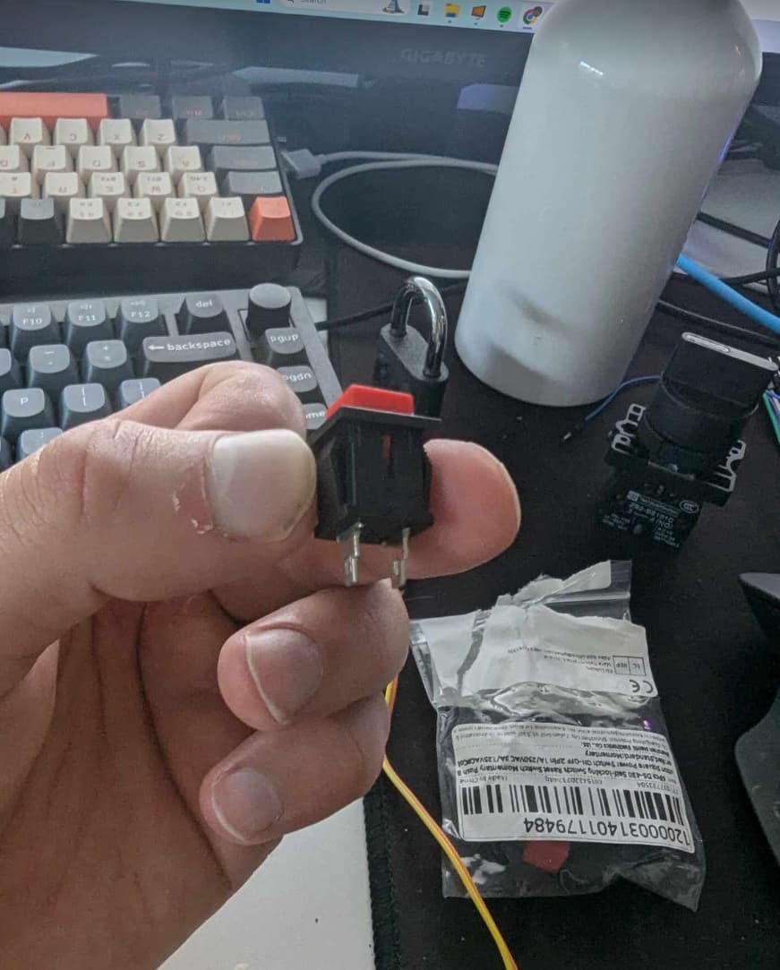
(EDIT: Rotary encoder connected like this rest to digital pins
My code is basically copy past and i do not know if sharing would help, if this is possible to set up it would be great if someone could put some example at least for button part. )
Please post your sketch, using code tags when you do. This prevents parts of it being interpreted as HTML coding and makes it easier to copy for examination
Which pins on the rotary encoder are those 5 wires connected to ?
In my experience the easiest way to tidy up the code and add the code tags is as follows
Start by tidying up your code by using Tools/Auto Format in the IDE to make it easier to read. Then use Edit/Copy for Forum and paste what was copied in a new reply. Code tags will have been added to the code to make it easy to read in the forum thus making it easier to provide help.
Please post an example of a guide where they read a rotary encoder with "voltage" (whatever that means). Are you sure that you're not confusing rotary encoders and potentiometers?
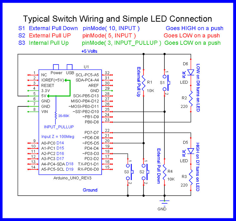
That can be connected as S3 in below image by @LarryD; use pinMode(yourPin, INPUT_PULLUP) in setup(). Or as S2 with an additional external pull-up resistor.
Rather than connect the switch across 0 and 1 like in your diagram, select a different digital pin, for example, 8, and program it as an input with input pull-up. Then you can connect the encoder button switch between that pin and ground to sense when the button has been pressed.
Like in the post above that happened while I was typing.
Okay, but then why when there are examples with one button ground is connected physically via pin and it's needed but when there are button matrix there is no ground connected and everything works fine?
In some keypad scan configurations, an output pin is used as a pseudo ground when it is set LOW, it is part of the scanning scheme, but why waste 2 digital pins for a single button.
If you have 5 pushbuttons then you would need 10 pins
I am just trying to understand step by step because in future I am planning to set up bunch of buttons. How does that pseudo ground is being set up? Is it in IDE maybe you have example with one button without those array lists? They confuse even more.
These guides shows blindly how to do it without understanding or deconstructing the process. What is happening under keypad library is unknow for me therefore it does not help to understand the process.