I have a doubt about if i should use a pullup resistor, when using the Default Button Exemple Code from Arduino IDE.
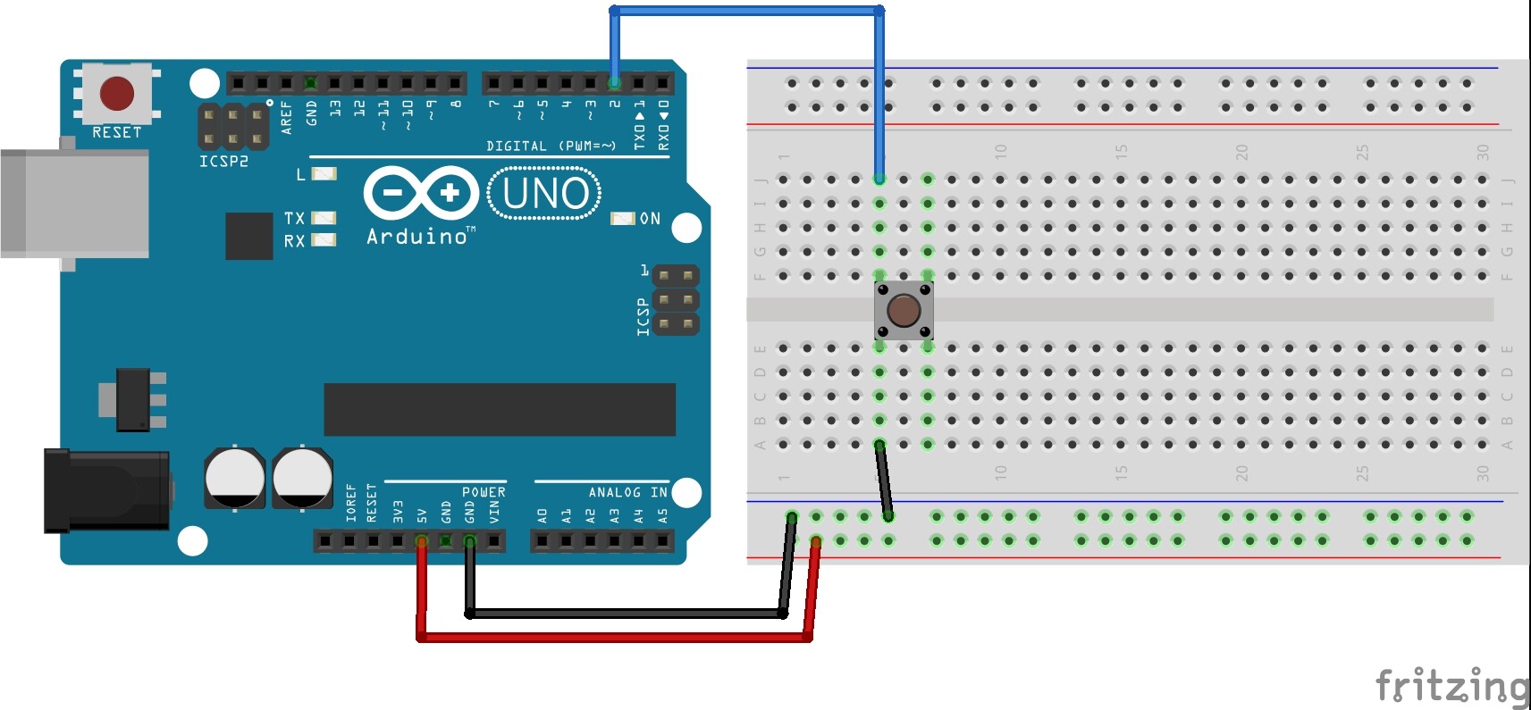
The idea is: to leave the pin13 LED ON and turn it off when i push the button. I wired as the pictures attached, both gave me the same result. But in the second one, i removed the pullup resistor.
The question, should i leave the pullup resistor or it's indifferent?
I need to understand the difference, because i'm working with this UnoJoy project, and to make the buttons work, i have to wire exactly as show in the pictures (not sure if it's correct, or if i should wire it another way)
As LarryD says the resistor should keep pin 2 pulled up to 5v when the button is not pushed otherwise it can float ( read either high or low at any time) .
Arduino has a built in pull up resistor on all I/o pins that can be activated by using INPUT_PULLUP
So the resistor is not really necessary .
I just copied the circuit on the Button Tutorial at Arduino.cc, the i wired GND and VCC on the opposite way to make the LED stays ON and turn OFF only the button is pressed.
But okay, i'll remake the circuit. Only question: WHY!?
I'm attaching a picture just to make sure. Is it correct?
Model 1 will never work because it is wired improperly - the two pins each side of the switch are internally connected. That means that either: the pullup is trying to pull up the side of the switch that is grounded; the pullup would need to go to the side of the switch that has the digital pin connected to it - OR - the pin and ground are connected, and pressing the button connects the pullup.
Part of the problem is that in the stupid fritzing diagrams, it's not clear which way the button is oriented.
The way the "Button" example is written pushing the button will drive pin 2 high. Here's what it says in the sketch:
 The circuit:
 * LED attached from pin 13 to ground
 * pushbutton attached to pin 2 from +5V
 * 10K resistor attached to pin 2 from ground

 * Note: on most Arduinos there is already an LED on the board
 attached to pin 13.
In practice it's simpler to leave the resistor out entirely and use the internal pull-up resistor. You'd just insert the button between pin 2 and ground. Then you'd change the code to set pin 2 to INPUT_PULLUP and change the logic so that it turns the LED on when LOW:
const int buttonPin = 2;     // the number of the pushbutton pin
const int ledPin =  13;      // the number of the LED pin

void setup()
{
    pinMode(ledPin, OUTPUT);
    pinMode(buttonPin, INPUT_PULLUP);
}

void loop()
{
    digitalWrite(ledPin, !digitalRead(buttonPin));
}
i wired GND and VCC on the opposite way to make the LED stays ON and turn OFF only the button is pressed.
You don't need to reverse the hardware. You can reverse the logic in your software sketch.
You can use a pull-up or a pull-down resistor as long as the switch "pulls" in the opposite direction. The switch/button has lower resistance when it's on (essentially zero resistance) so it dominates the over resistor. (The switch has infinite resistance when off and no current flows through it.)
But if you use a pull-down resistor, of course you should not enable the internal pull-up resistor.
And, it's more traditional to use a pull-up resistor and there are some circuits that only work with pull-ups.
Aaahh...i think the Circuit image made with Fritzing in this page https://www.arduino.cc/en/tutorial/button is wrong, because the schematics shows exactly what Hutkikz, DrAzzy and jboyton said. Thanks guys!
DVDdoug:
You don't need to reverse the hardware. You can reverse the logic in your software sketch.
You can use a pull-up or a pull-down resistor as long as the switch "pulls" in the opposite direction. The switch/button has lower resistance when it's on (essentially zero resistance) so it dominates the over resistor. (The switch has infinite resistance when off and no current flows through it.)
But if you use a pull-down resistor, of course you should not enable the internal pull-up resistor.
And, it's more traditional to use a pull-up resistor and there are some circuits that only work with pull-ups.
I have no idea how to make this via software. If i wire as the sketch says, the 13 pin LED will be OFF until i press the button. It's no big deal, since it's just to see how the pushbutton works. The problem: when i upload one of the .INO exemples of UnoJoy, after change the for the UnoJoy.hex firmware, if i go to "Control Panel > Devices and Printers > UnoJoy Joystick > Properties", it shows the "Button 3" pressed, and when i press the button, it shows as unpressed.
I know probably i'm not being very clear. If so, i'll make a small video of what is happening haha.