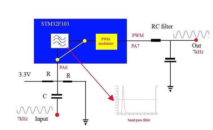
There must be a simple code for this circuit - sine in sine out. Any solution welcome.
(deleted)
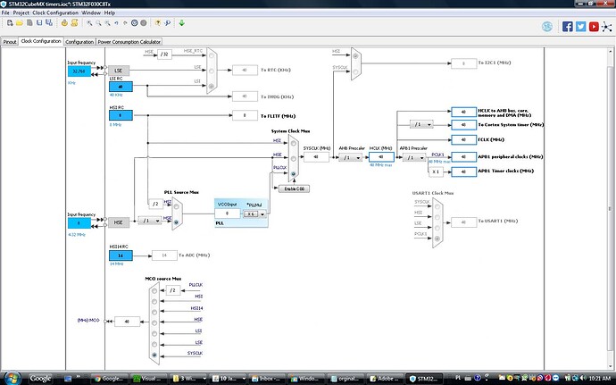
I tried, the problem is in default PWM frequency of stm32 board = 550Hz, as a result of that when I apply 7kHz modulating frequency is not a signal frequency but 5Hz. So after fitering the output will be 5Hz not 7kHz, will be because I dont have 5Hz RC filter. I think I need to use one of the stm32 timers = no idea haw to to that.
Of course it won't work like that.
I think you put the ADC in free running mode, timer OFV to adjust the OCR based on the ADC reading, but you may have speed problems here because you have at most a few clock cycles to sort it out... maybe you need to do this in the compare match interrupt instead to make sure you can set it up in time if the value is small (remember, you've got only a handful of processor cycles to do this). You're going to need to study the documentation for the timers and for the ADC, and use every trick in the book to get acceptable output - on both sides (the timer management and the ADC)... This is not something that you can trust to a library unless it's made for this exact thing. I think an STM32 can probably do it - they've got good timers and a good ADC and a much faster clock than the AVR series; I don't think you can do it on an AVR.
What the bloody hell do you need to regenerate a sine wave like that for?! Is this an XY problem?!
(deleted)
Presented solution may work but is not a simple one for programing beginner. If I can get it working I will put band pass filter between the pins. There are some examples on google but for very low frequences where detult PWM frequency is enough, and always output is for serial plotter not on the pin.From microcontroller I expecting a better performances than from switched capacitor filter (MSFS5) - currently used.
OP's other thread (@ted, please post a TL;DR here)
He wants to implement a digital filter on the STM32. Read analog input, filter, output as PWM, filter out PWM frequency.
For a 7 kHz signal you need a sample rate of at least 15 kHz (if you can minimize any noise > 7.5 kHz using an analog filter on the input). Let's assume that you can do that.
The next thing you have to check is if your filter code runs fast enough. You've only got 66 microseconds to sample, calculate and output.
That shouldn't be a problem if you're using low order filters. Implement your filter code in the loop, let it run freely, and check how long it takes.
You can speed up the sampling process by manipulating the ADC registers directly: read sample, start conversion, filter, output, repeat.
Instead of using analogRead: start conversion, wait for conversion to finish (wasted time), read sample, filter, output, repeat.
Or put it in free running mode, as suggested.
The next problem is getting the PWM frequency high enough. This is necessary, because you have to filter out this frequency in hardware, without filtering out the 7 kHz signal. Depending on the type of filter (RC or LC) you'll get a slope of -20dB/dec or -40dB/dec for your analog filter. You'll probably want to use an LC filter (or a second order filter) and a frequency of one decade higher than 7 kHz for approximately 40 dB of attenuation of the PWM frequency. (This depends on your needs, of course.)
That's 70 kHz, which is pretty high. Check the STM32's data sheet for information on how to set up the timers to output PWM at that frequency.
You'll probably want to put the sampling and filtering in a timer interrupt as well.
The question is: is all that really worth the effort?
Can't you just use a) an (active) analog band pass filter? b) a DSP unit that's designed for these kinds of tasks? or c) (if you really insist on using the STM32) at least get a DAC instead of hacking it with PWM.
Couldn't he use the DAC? Most stm32s have one...
I am using stm32f103 and LC filter. The LC filter is not a issue, it is working very good.
ted:
The LC filter is not a issue, it is working very good.
That doesn't say anything. What values are you using? Is it a simple LC low-pass? Your circuit in #2 shows an RC low-pass.
DrAzzy:
Couldn't he use the DAC? Most stm32s have one...
Check whether you can use the DAC first.
RC is on the drawing for simplicity (mostly used ) it is working not bad 10k/10nf , something like that - I used it long time ago, I have replaced R by L 10mH and C by 47nf, output - nice 20V sine wave.
Check whether you can use the DAC first.
I am using it in Voltmeter application.
Can't you just use a) an (active) analog band pass filter?
If you will use analog (double T) or similar and manage to get very narrow band the stability R and C a big issue.
So far I have sine wave generator 7kHz with timer setup for this frequency, sampling rate 700 kHz, so the PWM output frequency is ok. PWM on PB7 is modulated by sine generator, what is need is disabling the generator and modulate the PWM by signal applyed to PB0 .
#define SAMPLES 100
#include <libmaple/dma.h>

dma_tube_config dma_cfg, dma_cfg2;

int flag1 = 0;


int out1 = PB7;
//int inputPin  = PB0;  // analog input pin, inputPin = PB0; _ PA6

int val1[SAMPLES];

int16 shift = 0;

int amp = 35;
int cnt = 0;
int time_track = 0;
float stp = 6.2831 / SAMPLES;
int ret = 17;

timer_dev *dev1 = PIN_MAP[out1].timer_device;
uint8 cc_channel1 = PIN_MAP[out1].timer_channel;

void timer_conf()
{
  timer_dma_set_base_addr(dev1, TIMER_DMA_BASE_CCR2);
  timer_dma_set_burst_len(dev1, 1);
  timer_dma_enable_req(dev1, cc_channel1);
  timer_set_reload(dev1, 102);
  timer_set_prescaler(dev1, 0);

}

void dma_conf()
{
  dma_init(DMA1);
  /* T4C2 DMA C4 */
  dma_cfg.tube_dst = &(dev1->regs.gen->DMAR);
  dma_cfg.tube_dst_size = DMA_SIZE_32BITS;
  dma_cfg.tube_src = val1;
  dma_cfg.tube_src_size = DMA_SIZE_32BITS;

  dma_cfg.tube_nr_xfers = SAMPLES;
  dma_cfg.tube_flags = DMA_CFG_SRC_INC | DMA_CFG_CIRC | DMA_CFG_CMPLT_IE;

  dma_cfg.tube_req_src = DMA_REQ_SRC_TIM4_CH2;
  dma_cfg.target_data = 0;

  ret = dma_tube_cfg(DMA1, DMA_CH4, &dma_cfg);
}

void dma_start()
{


  dma_enable(DMA1, DMA_CH4);
  timer_resume(dev1);

  dma_enable(DMA1, DMA_CH2);

}

void init_wave()
{
  int i;
  for (i = 0; i < SAMPLES; i++)
  {
    val1[i] = 50 + amp * sin(stp * i);

  }
}

void get_wave(int16 shift)
{
  int i;
  for (i = 0; i < SAMPLES; i++);

}

void setup() {
  int i;
  pinMode(out1, PWM);
  //analogWrite(outputpin);   analogRead(inputpin));
  //pinMode ( ???);


  Serial.begin(9600);
  timer_conf();
  dma_conf();
  dma_start();
  init_wave();

}

void loop() {

}
Hi,
If you have a 550Hz PWM signal, you can only output a cycle every 1/550 = 0.0018181Seconds
or 1.8mS.
Your 7KHz signal is changing at 1/7000 = 1.428e-4Seconds
or 0.14mS
The update rate of the PWM is only 1.8mS
So how are you going to get any readable output.
The frequencies are not even harmonics of each other.
You may get the results you need using analog methods, but you need to review digital sampling methods.
After filtering I am not surprised you only get 5Hz.
Tom.... ![]()
PS. Can you draw what you expect the output of the controller to be, or what you expect modulating a lower 550Hz PWM with a higher 5kHz signal?
PPS. Have you looked at the specs of the controller you are using to see what PWM frequencies are available?
Tom
Thanks for explanation I am always Interested in such info.
Please look at post #1, 5 Hz is a side effect of my attempts. Currently I am working on post #14, on the drawing you can see my goal, fot now I am using a teporary yellow jumper.
Hi,
What is the PWM frequency of the STM chip?
Check the spec on the STM controller, see if there is a PWM library that will give you higher PWM, or some method of using the Timers in the controller chip.
While you have a low sample rate compared to the 7kHz input, you will not get 7kHz modulation of the PWM, your sample rate has to be at least twice the highest frequency of your input signal.
So your sampling should be at least 14kHz.
Google Nyquist Rate
Variable Speed Drives modulate PWM to get the varying output voltage AC frequencies, for just up to 100Hz modulation, they use a PWM frequency of many kHz, typically 8kHz.
Tom..... ![]()
STM32F103 is working at 72MHz, post # 14 is a 7kHz sine generator with PWM frequency 700 kHz , so I need to change the input of the modulator. Now modulation is from from sine generator and I need modulate PWM by signal applyed to PA6.


