PWM Fan Control-Board

Hey guys,

Currently I´m working on a circuit board for controlling a fan depending on temperature (in my case for a car or bike etc.).
The design and code derives from a project I have done in the past, which is working flawlessly until now.
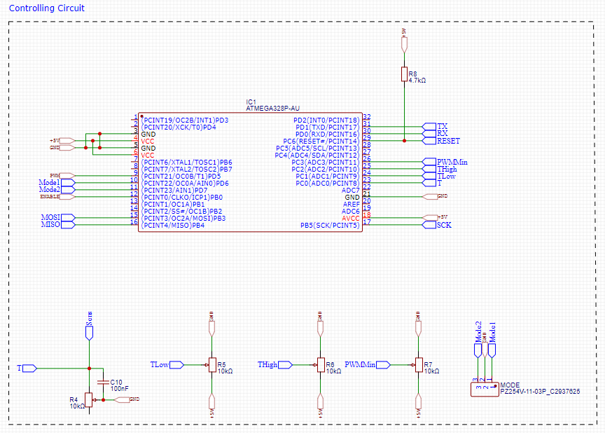
For the new design I just added a pin header to switch between different modes and changed to a different MOSFET, because the availability of the old one became terrible.
I´m using an Atmega328P with internal clock at 8MHz, programmed by an Arduino Uno as ISP, which I use for debugging (reading data from the Atmega and sending it to my PC via Serial).

So in theory everything should work fine if you started from a known, working design... but it doesn´t.

I encountered two problems:

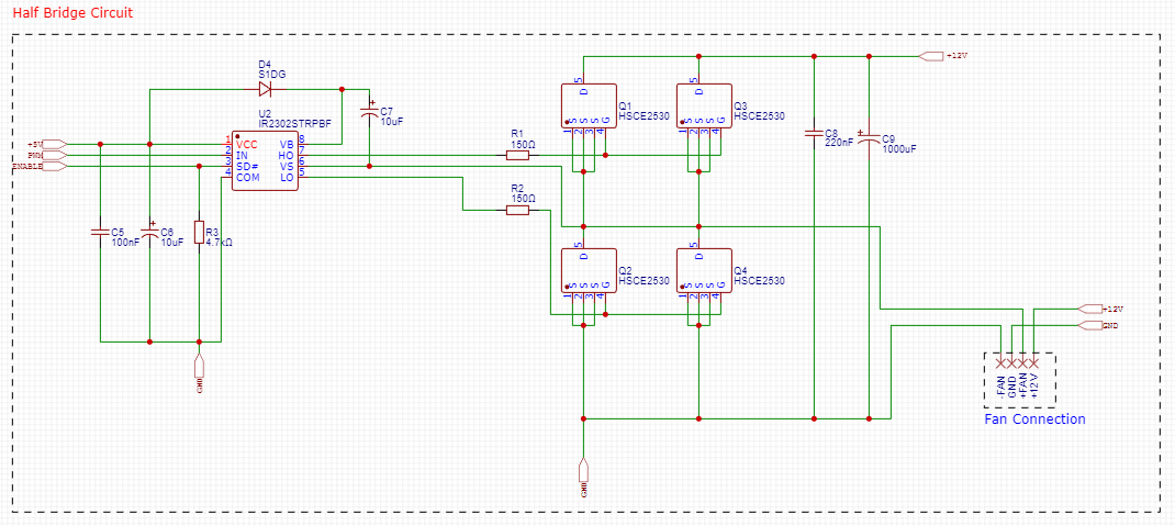
The first problem is that the pulldown resistor (R3) is not working. By that I mean no matter how big the value is, the Atmega is not able to pull the pin of the bridge driver high to enable it.
I tried values from 4.7k to 47k, but no difference. So I started to look after errors in my code regarding the logic and inversed it. Still no difference. I´m really scratching my head now, because this part of the pcb/code was working in the old design.

The second problem that the MOSFETs and the capacitor (C9) are getting really really hot after a short time. I run an old, small fan of a 3D-printer hot end for testing. My old design is capable of around 20A and is running very cool under these conditions.

Sadly, I can´t find the code of the old Arduino project....

Here is my code (still under construction :grin:) and I attached pictures of my schematic/PCB)

//Defining Pins
#define TPin PC0
#define TLowPin PC1
#define THighPin PC2
#define PWMMinPin PC3
#define PWMOutPin PD5
#define Mode1Pin PD6
#define Mode2Pin PD7
#define EnablePin PB0

//Constants
const int ntc_nom = 5000;
const int PWMMax = 255;

//Variables for temp measurement
float TRaw = 0;
float TU = 0;
float TR = 0;
float T = 0;

//Variables for parameters
int TLow = 0;
int THigh = 0;
int PWMMin = 0;
int PWMOut = 0;
int Mode1 = false;
int Mode2 = false;
int FanState = 0;

//This makes printing values much easier (for debugging)
void printValue(String text, float value, String text2 = "");

void setup() {
  //Pin setup
  pinMode(TPin, INPUT);
  pinMode(TLowPin, INPUT);
  pinMode(THighPin, INPUT);
  pinMode(PWMMinPin, INPUT);
  pinMode(PWMOutPin, OUTPUT);
  pinMode(Mode1Pin, INPUT_PULLUP);
  pinMode(Mode2Pin, INPUT_PULLUP);
  pinMode(EnablePin, OUTPUT);

  Serial.begin(9600);

  //Reading the potentiometers to get the parameters and mapping them to fixed values
  TLow = analogRead(TLowPin);
  TLow = map(TLow, 0, 1023, 0, 120);

  THigh = analogRead(THighPin);
  THigh = map(THigh, 0, 1023, 0, 120);

  PWMMin = analogRead(PWMMinPin);
  PWMMin = map(PWMMin, 0, 1023, 0, 255);

  //Turning off the mosfet driver at startup
  digitalWrite(EnablePin, LOW);

}

void loop() {
  
  //Reading the mode pins to choose the mode
  Mode1 = digitalRead(Mode1Pin);
  Mode2 = digitalRead(Mode2Pin);

  //Mode 1
  if(Mode1 == 0 && Mode2 == 1) {
  
  //Getting the temperature
  TRaw = analogRead(TPin);
  TU = TRaw * 5 / 1023;
  TR = ntc_nom * (5 / TU - 1);
  T = -28.42 * log(TR) + 234.33;

  //Turning fan on when TLow is reached and setting PWM signal according to the parameters
  if(T >= TLow){
    PWMOut = map(T, TLow, THigh, PWMMin, 255);
    PWMOut = constrain(PWMOut, PWMMin, 255);
    analogWrite(PWMOutPin, PWMOut);
    digitalWrite(EnablePin, HIGH);
    FanState = 1;

  }
  //If temperature drops below TLow the fan is switched off
  else{
    analogWrite(PWMOutPin, 0);
    digitalWrite(EnablePin, LOW);
    FanState = 0;
  }

  //Debugging
  Serial.println("MODE 1");
  printValue("T: ", T);
  printValue("TLow: ", TLow);
  printValue("THigh: ", THigh);
  printValue("PWMMin: ", PWMMin);
  printValue("Mode1: ", Mode1);
  printValue("Mode2: ", Mode2);
  printValue("PWMOut: ", PWMOut);
  printValue("FanState: ", FanState);
  Serial.println();
  delay(1000);
  }

  //Mode 2
  if(Mode1 == 1 && Mode2 == 0){
    analogWrite(PWMOutPin, 200);
    digitalWrite(EnablePin, HIGH);
    FanState = 1;

  //Debugging
  Serial.println("MODE 2");
  printValue("T: ", T);
  printValue("TLow: ", TLow);
  printValue("THigh: ", THigh);
  printValue("PWMMin: ", PWMMin);
  printValue("Mode1: ", Mode1);
  printValue("Mode2: ", Mode2);
  printValue("PWMOut: ", PWMOut);
  printValue("FanState", FanState);
  Serial.println();
  delay(1000);

  }

  //Mode 3
  if(Mode1 == 1 && Mode2 == 1){
  //coming soon

  }
}

void printValue(String text, float value, String text2 = "") {
  Serial.print(text);
  Serial.print(value);
  Serial.println(text2);
}


2 Likes

Check for a short circuit or lack of continuity on the PCB.

If I remove R3 everything is working fine, but then I´m no longer able to disable the driver.
I got continuity between the Atmega and the driver pins.
I measured around 400kOhm between the trace and ground and 1MOhm between trace and the 5V network.

Could be a problem with the ATmega chip.

That's a possibility, pretty easy to short these tiny pins while fiddling around with a multimeter...

I will build a second board for testing.

The heat problem is another story...

The schematic does not show the required decoupling capacitors for the ATmega328. They are not optional.

The second problem that the MOSFETs and the capacitor (C9) are getting really really hot after a short time.

That suggests that the bootstrap gate driver is not working properly, so the MOSFETs are not turning on completely.

The caps of the "power supply circuit" (C3 & C4) are not enough? Hmm... that´s not easy to solve without a new PCB :thinking:

If that´s the case I shouldn´t have this problem on the second board (when I´m done building it...), right?

Definitely not. Typical examples are 100 nF ceramic, located as close to the appropriate MCU pins as possible. They are found on every professional PCB design for the ATmega328.

Which ones? Q2 and Q4 by any chance, more so than Q1 and Q3?

I'm wondering about this, which is the typical application of the bridge driver you're using:
image
Vs. your implementation, which seems to deviate from this.

Also, out of curiosity - given the ratings of the MOSFETs you're using here (HSCE2530), why are you using two each for the high and low side? They appear pretty capable; what kind of gigantic fan are you trying to drive given that you need four of them?

Edit: thinking about this some more, I'd really recommend going back to the datasheet of the IR2303 bridge driver and analyzing your own implementation against the typical connection and the functional block diagram in the datasheet.

For instance, when LO goes high, you're discharging C7 directly into GND. That's about all that Q2 and Q4 seem to be doing there; they don't affect the load (fan) because it seems you've got the fan- tied to GND anyway. At a low PWM frequency, this doesn't hurt much, but if you go up into the kHz range, you'll start dissipating significant power there.

I'm also puzzled why you're running the driver at 5V.

Why are you using a half bridge to drive a fan?

1 Like

Thank you very much for your reply, you are right.
I don´t know why I derived from the application in the datasheet, that was a mistake. But I still wonder, why it worked in the old design with the 240W fan, it should get as hot as the new (worse) design.

These mosfets are cheap and so I drive them paralell to lower their "resistance" to lower heat.
I plan on using this circuit for up to 30A @ 12V.

I do this, so I just need one "power supply" on my PCB. If I wanted to run it at, let´s say 12V, I would need to "clean up" the noisy 12V network of a car/bike.

I just tested something different (by accident). I removed C9 and now nothing gets hot, at least with the puny 40mm fan.

Sorry, I don´t understand this question? Because I don´t need a full bridge? :sweat_smile:

May have something to do with the specs of the MOSFETs which perhaps prevented them the lower ones from switching on. Just guessing. What type did you use?

Whoops, OK! Those are serious currents indeed.

Can't quite explain that, to be honest! Maybe it depends on the source impedance of your 12V supply, but that's a stretch.

I see. I'd be inclined to measure the gate voltage when turned on for the high side MOSFETs to see if that is high enough to switch them fully on.

I'm with @jim-p here. Just use a regular low-side switch with a suitably low Rds(on). The MOSFETs you've got would be very suitable for this. Combine two if you like.

You don't need any bridge at all.

I used Infineon IPB011N04LG

Sadly, I got nothing to measure that....

You mean just use a mosfet as a switch? Like a very very very fast light switch to control RPM?
What about the time, when the mosfet is switched off? Is there no problem with the integrated diode of the mosfet?

Sorry, I don´t understand this question? Because I don´t need a full bridge?

Why do you need any kind of bridge do drive a DC fan?
Maybe you should re-think this entire design and start over.
It can probably be done much much simpler

Does the fan ever reverse? If one side of the fan is grounded, then Q2 and Q4 could be replaced by a flyback diode.

I feel like I should tell you a little more about my application and what led me to my approach.
The circuit is meant to control the speed of a radiator fan in a car depending on engine temperature.
In big engines a radiator fan can reach up to 30A.
The fan can be spun backwards if you drive fast enough (with the car, not the fan).

In one of my first tries I used a single mosfet with a flyback diode, but the induced currents while the mosfet was switched off but still running (so at like 50% duty cycle) where too high for a diode. Both leads of the fan were connected to my circuit.

After talking to a buddy who does more tinkering with electronics than me, he suggested a half bridge instead of a flyback diode.
That's why I am where I am with my design. Derivations of the typical application suggestion of the driver not intended.

I understand the problem but the half bridge was not the solution. When the PWM is off so are both MOSFETs.
However, I don't see why a heavy duty flyback would not solve the problem

Is there a way to calculate the ratings of a flyback diode?

If it a 60A fan I can't see it generation more he 60A when spinning backwards. I doubt if it can generate more than 1A but it's the power dissipation of the diode that is important. You may need a 10-20A diode in a nice big package