Hi,
If you are trying to clean up a noisy sinewave signal, this will not do it?
OPs signal.
Tom.. ![]()
Hi,
If you are trying to clean up a noisy sinewave signal, this will not do it?
OPs signal.
Tom.. ![]()
Hi,
If you are trying to clean up a noisy sine wave signal, this will not do it?
Smoothing filter exactly should do that.
OMG
An analog output is PWM, it is not analog !
I have another program - sine wave generator with PWM output, using RC filter I have from PWM sine, with LC filter I have wery clean sine.
Tom
How you put my drawing in the post ?
When I click - insert picture - there is only option for link, so I used attachment option.
In signal serial plotter the signal is ok
When I compare PWM from sine generator with smoothing filter PWM they different,
the first one is blurred the second one is a clear square wave with visible with modulation.
In serial plotter the signal is ok
When I compare PWM from sine generator with smoothing filter PWM they different,
the first one is blurred the second one is a clear square wave with visible with modulation.

ted:
In serial plotter the signal is okWhen I compare PWM from sine generator with smoothing filter PWM they different,
the first one is blurred the second one is a clear square wave with visible with modulation.
PWM from sine generator... what do you mean?
A PWM modulated by the sinewave is what you get, do you want a sinewave output.
The reason your monitor waveform is sinusoidal is because you are reading the dutycycle value of your filter, the duty cycle being modulated by your sinewave input.
You can try and use a LP filter on the output to get your PWM to convert to analog sinewave.
https://arduino-info.wikispaces.com/Analog-Output
Tom.. ![]()
PWM from sine generator... what do you mean?
I have two programs and I am comparing the shape of PWM of both.
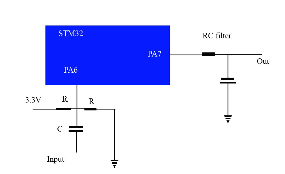
I have this filter
For sine wave generator frequency of PWM pulses is 100 times higher then frequency of sine wave, in smoothing program is 550 Hz, dividing it by 100 =5.5Hz, so this program is ok for very low frequences - rotating speed of the potentiometer.
Hi,
Okay I think I understand.
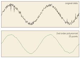
You are feeding your noisy analog signal into the controller and using smoothing aiming to get rid of the noise.
You are happy with the sinewave modulated PWM output.
You are comparing this sinewave modulated output with a signal generator produced sinewave modulated PWM.
How are you synchronizing your scope?
Are your PWM frequencies the same?
Is the noisy sinewave in phase with the sinewave you are modulating the the sig gen PWM with?
Are you synching the scope to the analog sinewave?
If your scope sync is not right, one channel will always appear to have blurring duty cycle.
Tom.... ![]()
Ohh great, you have a proper CRO.. Yes.. ![]()
![]()
![]()
But image on left screen lower line is different than on serial plotter - post #47, as far I now arduino default frequency is 450 Hz or 550Hz, so I need to change it some how.
Hi Ted,
You asked me to join this discussion. What is it you need help with exactly?
And what is it you're trying to do? From what I understand, you want to read a noisy sine wave input denoise it using digital filters, then modulate it as PWM, and use an analog low-pass filter to filter out the PWM frequency again. Is that correct?
Pieter
Hi Pieter
Thanks for reply
I am interested in digital filters to see what they can do in practice, to compare them with Switched Capacitor Filters (max7400, MSFS 5). I generate the code for filter using
https://www-users.cs.york.ac.uk/~fisher/mkfilter/trad.html .
I am jus trying to figure out how to implement generated code, to have input and output of the filter on pins of stm32.
So far what I did code
int inputPin  = PA6;  // analog input pin
int outputPin = PA7; //output pin

void setup() {
  // put your setup code here, to run once:
 pinMode(inputPin, INPUT_ANALOG);
  pinMode(outputPin, OUTPUT);


  Serial.begin(9600);
}

void loop() {
  // put your main code here, to run repeatedly:

}


2.11910705e+07,   1.00000000e+00,  0.00000000e+00, -8.00000000e+00 , 0.00000000e+00
2.80000000e+01 , 0.00000000e+00, -5.60000000e+01,  0.00000000e+00 , 7.00000000e+01
0.00000000e+00 , -5.60000000e+01,  0.00000000e+00 , 2.80000000e+01 , 0.00000000e+00
- 8.00000000e+00,  0.00000000e+00,  1.00000000e+00, -9.68306496e-01 , 1.53576283e+01
- 1.14342436e+02,  5.30474126e+02, -1.71641864e+03,  4.10708725e+03 , -7.51791136e+03
1.07384685e+04 , -1.20964741e+04 , 1.07817869e+04, -7.57868735e+03 , 4.15699129e+03
- 1.74428242e+03,  5.41260309e+02, -1.17138001e+02  , 1.57965742e+01, -1.00000000e+00


/* Digital filter designed by mkfilter/mkshape/gencode   A.J. Fisher
   Command line: /www/usr/fisher/helpers/mkfilter -Bu -Bp -o 8 -a 2.2833333333e-02 2.3833333333e-02 -l */

#define NZEROS 16
#define NPOLES 16
#define GAIN   2.119107055e+07

static float xv[NZEROS+1], yv[NPOLES+1];

static void filterloop()
  { for (;;)
      { xv[0] = xv[1]; xv[1] = xv[2]; xv[2] = xv[3]; xv[3] = xv[4]; xv[4] = xv[5]; xv[5] = xv[6]; xv[6] = xv[7]; xv[7] = xv[8]; xv[8] = xv[9]; xv[9] = xv[10]; xv[10] = xv[11]; xv[11] = xv[12]; xv[12] = xv[13]; xv[13] = xv[14]; xv[14] = xv[15]; xv[15] = xv[16];
        xv[16] = `next input value' / GAIN;
        yv[0] = yv[1]; yv[1] = yv[2]; yv[2] = yv[3]; yv[3] = yv[4]; yv[4] = yv[5]; yv[5] = yv[6]; yv[6] = yv[7]; yv[7] = yv[8]; yv[8] = yv[9]; yv[9] = yv[10]; yv[10] = yv[11]; yv[11] = yv[12]; yv[12] = yv[13]; yv[13] = yv[14]; yv[14] = yv[15]; yv[15] = yv[16];
        yv[16] =   (xv[0] + xv[16]) - 8 * (xv[2] + xv[14]) + 28 * (xv[4] + xv[12])
                     - 56 * (xv[6] + xv[10]) + 70 * xv[8]
                     + ( -0.9683064956 * yv[0]) + ( 15.3576282530 * yv[1])
                     + (-114.3424355200 * yv[2]) + (530.4741262700 * yv[3])
                     + (-1716.4186422000 * yv[4]) + (4107.0872513000 * yv[5])
                     + (-7517.9113582000 * yv[6]) + (10738.4685320000 * yv[7])
                     + (-12096.4741070000 * yv[8]) + (10781.7869080000 * yv[9])
                     + (-7578.6873535000 * yv[10]) + (4156.9912921000 * yv[11])
                     + (-1744.2824180000 * yv[12]) + (541.2603088000 * yv[13])
                     + (-117.1380007100 * yv[14]) + ( 15.7965742420 * yv[15]);
        `next output value' = yv[16];
      }
  }
That code doesn't compile. You don't use the filter function, and you didn't specify an input or output.
Did you try the example included with my Filter library I linked to earlier?
You need to know the coefficients of the transfer function of the filter. They are generated by the filter design tool. They are te coefficients in the difference equation. The algorithm you posted just calculates the result of te difference equation. I think it's well explained on the Wikipedia page on IIR filters.
I am trying to modify yourlinked example, this is what I did
#include <FIRFilter.h>
#include <IIRFilter.h>

#define NZEROS 16
#define NPOLES 16
#define GAIN   2.119107055e+07

int inputPin  = PA6;  // analog input pin
int outputPin = PA7; //output pin


/*// 35 Hz Butterworth low-pass
const float b_lp[] = { 0.00113722762905776, 0.00568613814528881, 0.0113722762905776,  0.0113722762905776,  0.00568613814528881, 0.00113722762905776 };
const float a_lp[] = { 1, -3.03124451613593, 3.92924380774061,  -2.65660499035499, 0.928185738776705, -0.133188755896548 };
*/

//7kHz Hz Butterworth band-pass filter
const float a_bp[] =
{
2.11910705e+07,   1.00000000e+00,  0.00000000e+00, -8.00000000e+00 , 0.00000000e+00,
2.80000000e+01 , 0.00000000e+00, -5.60000000e+01,  0.00000000e+00 , 7.00000000e+01,
0.00000000e+00 , -5.60000000e+01,  0.00000000e+00 , 2.80000000e+01 , 0.00000000e+00,
- 8.00000000e+00,  0.00000000e+00,  1.00000000e+00, -9.68306496e-01 , 1.53576283e+01,
- 1.14342436e+02,  5.30474126e+02, -1.71641864e+03,  4.10708725e+03 , -7.51791136e+03,
1.07384685e+04 , -1.20964741e+04 , 1.07817869e+04, -7.57868735e+03 , 4.15699129e+03,
- 1.74428242e+03,  5.41260309e+02, -1.17138001e+02  , 1.57965742e+01, -1.00000000e+00,
};


/*        // 0.3 Hz high-pass
const float b_hp[] = { 1, -1 };
const float a_hp[] = { 1, -0.995 };

FIRFilter notch(b_notch);
IIRFilter lp(b_lp, a_lp);
IIRFilter hp(b_hp, a_hp);
*/
void setup()
{
  // put your setup code here, to run once:
 pinMode(inputPin, INPUT_ANALOG);
  pinMode(outputPin, OUTPUT);

}
  Serial.begin(9600);
}
void loop() { /*
  const static unsigned long ECG_interval  = round(1e6 / ECG_samplefreq);
  static unsigned long ECG_prevmicros = micros();

  if (!Serial) {
    ECG_prevmicros = micros();
  } else if (micros() - ECG_prevmicros >= ECG_interval) {
    measureECGAndSend();
    ECG_prevmicros += ECG_interval;*/

static float xv[NZEROS+1], yv[NPOLES+1];

static void filterloop()
  { for (;;)
      { xv[0] = xv[1]; xv[1] = xv[2]; xv[2] = xv[3]; xv[3] = xv[4]; xv[4] = xv[5]; xv[5] = xv[6]; xv[6] = xv[7]; xv[7] = xv[8]; xv[8] = xv[9]; xv[9] = xv[10]; xv[10] = xv[11]; xv[11] = xv[12]; xv[12] = xv[13]; xv[13] = xv[14]; xv[14] = xv[15]; xv[15] = xv[16];
        xv[16] = 'next input value' / GAIN;
        yv[0] = yv[1]; yv[1] = yv[2]; yv[2] = yv[3]; yv[3] = yv[4]; yv[4] = yv[5]; yv[5] = yv[6]; yv[6] = yv[7]; yv[7] = yv[8]; yv[8] = yv[9]; yv[9] = yv[10]; yv[10] = yv[11]; yv[11] = yv[12]; yv[12] = yv[13]; yv[13] = yv[14]; yv[14] = yv[15]; yv[15] = yv[16];
        yv[16] =   (xv[0] + xv[16]) - 8 * (xv[2] + xv[14]) + 28 * (xv[4] + xv[12])
                     - 56 * (xv[6] + xv[10]) + 70 * xv[8]
                     + ( -0.9683064956 * yv[0]) + ( 15.3576282530 * yv[1])
                     + (-114.3424355200 * yv[2]) + (530.4741262700 * yv[3])
                     + (-1716.4186422000 * yv[4]) + (4107.0872513000 * yv[5])
                     + (-7517.9113582000 * yv[6]) + (10738.4685320000 * yv[7])
                     + (-12096.4741070000 * yv[8]) + (10781.7869080000 * yv[9])
                     + (-7578.6873535000 * yv[10]) + (4156.9912921000 * yv[11])
                     + (-1744.2824180000 * yv[12]) + (541.2603088000 * yv[13])
                     + (-117.1380007100 * yv[14]) + ( 15.7965742420 * yv[15]);
      }
{
  'next output value' = yv[16];
}

  }
}

void measureECGAndSend() {
  int16_t value = analogRead(ECG_pin);
  float filtered = notch.filter(
                      lp.filter(
                      hp.filter(value - DC_offset)));
  value = round(filtered) + DC_offset;
  Serial.println(value);
}