Hi all
I'm new to tiny programing and i did a little research and foynd these two images (attached below)
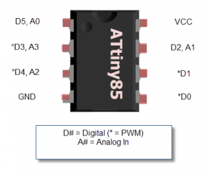
The first diagram says the tiny45/85 has has 3 analog inputs and two PWM outputs,whereas in the second one it says it has 4 analog inputs and 5 PWM outputs-of course not all together because there are only 6 pins of I/O.
Those of you how experimented with this chip: which one is? Which one is true? Maybe neither?
Thank you for your help
There are 4 PWM pins, BUT... one of them, if enabled, will always be the inverse of the other (i.e. if one pin is high, the other is low).
There are 4 analog inputs, BUT... one of them is multiplexed with the Reset pin, which cannot be used unless you have a high voltage programmer or bootloader as disabling the reset pin prevents the use of ISP.
The remark about one being the inverse of the other is not entirely true. The Attiny85 has a dead time generator which allows the two to have a slightly different duty cycle, but this is not the same thing as having two independently controllable outputs. See page 106 of the datasheet for more info.