Questions about logging RTC data to SD card using Millis

Hi Everyone, just a quick disclaimer. I am relatively new to Arduino and I am not a programmer.

I am trying to use a DS3231 RTC with a micro SD card module and a 0.9" oled display. The end goal is to have a small unit that displays date, time, temperature and logs the same to a micro SD card. The project is based on the WayinTop "example" that is provided when you buy their Oled/RTC/SD kit. The example only includes the display portion of the project and does not address the storage portion. I have looked at and used the SD storage example that can be found at "How to Mechatronics".

My current issue:

  1. The SD example uses the D3231 library to store data with the SD library.
  2. The Oled display/RTC module uses the wire library to pull RTC data and display
  3. When I attempt to merge these two examples I do not get a useable sketch.
    a) I have used Wire to maintain the display portion of the sketch as well as adding the DS3231 library and similar logging
    b) I end up with a sketch that will compile and upload but no luck with actually logging data.
    c) In the serial monitor i get two vertical arrows and nothing else (I have not specified this in the code as far as I know)
    d) I have tried to remove the 3 second delay from the data logging example and replace it with Millis, again, compiles and uploads but no function......

Troubleshooting till now:

  1. library reviews - all libraries used work individually in similar sketches
  2. Forum and google reviews - nobody seems to be using a similar configuration as i am.
  3. Several hours of error message review and troubleshooting to get to a code that compiles.

Can someone please help me understand where I have gone wrong and what I can try to fix it? Please note again that I NOT a programmer, please do what you can to explain in laymen's terms. current script attached.

Edit: Adding info

  1. Logging interval every 60 seconds
  2. Temp signal directly from DS3231
  3. UNO for prototyping & nano for final integration

DS3231_Temp_store.ino (12.2 KB)

1. At what interval you want to store temperature data along with date-time stamp on the SD card.

2. Are you acquiring temperature signal from the internal temperature sensor of DS3231?

3. What Arduino (UNO/NANO/MEGA) you are using.

  1. the fastest I would be trying to store is ever minute.
  2. yes the temperature should be acquired from the DS3231.
  3. Prototyping on UNO, final integration on Nano.

Let us follow every step of this tutorial. When a step is done, then put a tick mark on it. After the expected result has been achieved, we may slowly study the functions of the codes lines of the sketch.

1. Connect DS3231 Module as per diagram of Fig-1.
rtc-sm-sd.png
Figure-1:

2. Upload the following sketch.

#include <Wire.h>
#include "RTClib.h"   // Jeelab's fantastic RTC library. 
RTC_DS3231 rtc;
byte prMin = 0;
byte x;

void setup ()
{
  Serial.begin(9600);
  Wire.begin();
  rtc.begin();
  rtc.adjust(DateTime(F(__DATE__), F(__TIME__)));
  //rtc.adjust(DateTime(2021, 12, 31, 11, 59, 57));//set date-time manualy:yr,mo,dy,hr,mn,sec
}

void loop ()
{
  showDate();     //show date on Serial Monitor
  showTime();    //Current time: 24 Hrs
  showTemp();   //show temperature
  timeDelay();  //2 minute time delay as counted by RTC
}

//===================================================
void showDate()
{
  DateTime nowDT = rtc.now();
  Serial.print(nowDT.day(), DEC); Serial.print('/');
  Serial.print(nowDT.month(), DEC); Serial.print('/');
  Serial.print(nowDT.year(), DEC); Serial.print(" ==> ");
}

void showTime()
{
  DateTime nowDT = rtc.now();
  Serial.print(nowDT.hour(), DEC); Serial.print(':');
  //-------------------------------------------------
  byte myMin = nowDT.minute();
  if (myMin < 10)
  {
    Serial.print('0');
  }
  Serial.print(nowDT.minute(), DEC); Serial.print(':');
  //--------------------------------------------------
  byte mySec = nowDT.second();
  if (mySec < 10)
  {
    Serial.print('0');
  }
  Serial.print(nowDT.second(), DEC);
}
//---------------------------------------------
void timeDelay()
{
  prMin = bcdMinute();   //current second of RTC
  while (bcdMinute() - prMin != 1)
  {
    ;
  }
  prMin = bcdMinute(); //delay(1000);
}

byte bcdMinute()
{
  DateTime nowTime = rtc.now();
  if (nowTime.minute() == 0 )
  {
    prMin = 0;
    return prMin;
  }
  else
  {
    DateTime nowTime = rtc.now();
    return nowTime.minute();
  }
}

void showTemp()
{
  float myTemp = rtc.getTemperature();
  Serial.print("  Temperature: ");
  Serial.print(myTemp, 2);
  Serial.println(" degC");
}
//==========================================

2. Observe that the Serial Monitor shows the current date, time in 24-Hrs format, and temperature at 1-min interval (Fig-2). The current date and time are taken from PC; however, the user can (if he wishes) set it manually in the setup() function of the sketch by manipulating the following codes:

rtc.adjust(DateTime(F(__DATE__), F(__TIME__))); //takes data time from PC
  //rtc.adjust(DateTime(2021, 12, 31, 11, 59, 57));//set date-time manualy:yr,mo,dy,hr,mn,sec

SMq12.png
Figure-2:

3. Functional Check of SD Card.
(1) Connect SD card with UNO as per Fig-1.
(2) Upload the following sketch into UNO to verify that this string "Forum" could be written and read to/from SD card correctly.

//SIMPLE WRITE AND READ

#include<SPI.h>   //sd cARD USES spi bUS
#include<SD.h>    //contains library functions

#define CSPIN 4   //if using DPin-4, it does not require to set direction
File myFile;      //file pointer variavle declaration

void setup()
{
  Serial.begin(9600);
 pinMode(CSPIN, OUTPUT);
  delay(1000);
  if (!SD.begin(CSPIN)) 
  {
    Serial.println("Card failed, or not present");
    return;
  }
  Serial.println("card initialized.");
 // SD.begin(CSPIN);        //SD Card is initialized
  SD.remove("Test.txt"); //remove any existing file with this name
  myFile = SD.open("Test.txt", FILE_WRITE);  //file created and opened for writing

  if (myFile)       //file has really been opened
  {
    myFile.println("Forum"
    );
  }
  myFile.close();
  myFile = SD.open("Test.txt", FILE_READ);  //file opened for reading

  if (myFile)       //file has really been opened
  {
    while (myFile.available())
    {
      Serial.print((char)myFile.read());
    }
    myFile.close();
  }
}

void loop()
{

}

4. Upload the following sketch to begin temperature logging onto SD card and Serial Monitor when swicth K1 is pressed.
.......... (left for OP)

rtc-sm-sd.png

SMq12.png

GolamMostafa:
Let us follow every step of this tutorial. When a step is done, then put a tick mark on it. After the expected result has been achieved, we may slowly study the functions of the codes lines of the sketch.

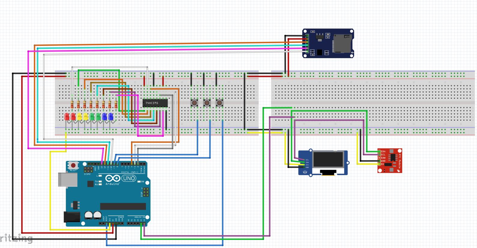
1. Connect DS3231 Module as per diagram of Fig-1. -DONE
rtc-sm-sd.png
Figure-1:

2. Upload the following sketch. -DONE

#include <Wire.h>

#include "RTClib.h"   // Jeelab's fantastic RTC library.
RTC_DS3231 rtc;
byte prMin = 0;
byte x;

void setup ()
{
 Serial.begin(9600);
 Wire.begin();
 rtc.begin();
 rtc.adjust(DateTime(F(DATE), F(TIME)));
 //rtc.adjust(DateTime(2021, 12, 31, 11, 59, 57));//set date-time manualy:yr,mo,dy,hr,mn,sec
}

void loop ()
{
 showDate();     //show date on Serial Monitor
 showTime();    //Current time: 24 Hrs
 showTemp();   //show temperature
 timeDelay();  //2 minute time delay as counted by RTC
}

//===================================================
void showDate()
{
 DateTime nowDT = rtc.now();
 Serial.print(nowDT.day(), DEC); Serial.print('/');
 Serial.print(nowDT.month(), DEC); Serial.print('/');
 Serial.print(nowDT.year(), DEC); Serial.print(" ==> ");
}

void showTime()
{
 DateTime nowDT = rtc.now();
 Serial.print(nowDT.hour(), DEC); Serial.print(':');
 //-------------------------------------------------
 byte myMin = nowDT.minute();
 if (myMin < 10)
 {
   Serial.print('0');
 }
 Serial.print(nowDT.minute(), DEC); Serial.print(':');
 //--------------------------------------------------
 byte mySec = nowDT.second();
 if (mySec < 10)
 {
   Serial.print('0');
 }
 Serial.print(nowDT.second(), DEC);
}
//---------------------------------------------
void timeDelay()
{
 prMin = bcdMinute();   //current second of RTC
 while (bcdMinute() - prMin != 1)
 {
   ;
 }
 prMin = bcdMinute(); //delay(1000);
}

byte bcdMinute()
{
 DateTime nowTime = rtc.now();
 if (nowTime.minute() == 0 )
 {
   prMin = 0;
   return prMin;
 }
 else
 {
   DateTime nowTime = rtc.now();
   return nowTime.minute();
 }
}

void showTemp()
{
 float myTemp = rtc.getTemperature();
 Serial.print("  Temperature: ");
 Serial.print(myTemp, 2);
 Serial.println(" degC");
}
//==========================================


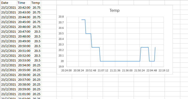
**2.** Observe that the Serial Monitor shows the current date, time in 24-Hrs format, and temperature at 1-min interval (Fig-2). The current date and time are taken from PC; however, the user can (if he wishes) set it manually in the setup() function of the sketch by manipulating the following codes: -DONE


rtc.adjust(DateTime(F(DATE), F(TIME))); //takes data time from PC
 //rtc.adjust(DateTime(2021, 12, 31, 11, 59, 57));//set date-time manualy:yr,mo,dy,hr,mn,sec


![SMq12.png|605x448](upload://qkePspfvvV71EKGmKMsA2VwD8Vo.png)
Figure-2:

**3.** Functional Check of SD Card. -DONE
**(1)** Connect SD card with UNO as per Fig-1.
**(2)** Upload the following sketch into UNO to verify that this string "Forum" could be written and read to/from SD card correctly.


//SIMPLE WRITE AND READ

#include<SPI.h>   //sd cARD USES spi bUS
#include<SD.h>    //contains library functions

#define CSPIN 4   //if using DPin-4, it does not require to set direction
File myFile;      //file pointer variavle declaration

void setup()
{
 Serial.begin(9600);
pinMode(CSPIN, OUTPUT);
 delay(1000);
 if (!SD.begin(CSPIN))
 {
   Serial.println("Card failed, or not present");
   return;
 }
 Serial.println("card initialized.");
// SD.begin(CSPIN);        //SD Card is initialized
 SD.remove("Test.txt"); //remove any existing file with this name
 myFile = SD.open("Test.txt", FILE_WRITE);  //file created and opened for writing

if (myFile)       //file has really been opened
 {
   myFile.println("Forum"
   );
 }
 myFile.close();
 myFile = SD.open("Test.txt", FILE_READ);  //file opened for reading

if (myFile)       //file has really been opened
 {
   while (myFile.available())
   {
     Serial.print((char)myFile.read());
   }
   myFile.close();
 }
}

void loop()
{

}


**4.** Upload the following sketch to begin temperature logging onto SD card and Serial Monitor when swicth K1 is pressed.
.......... (left for OP)

Thank you for your support, both of these items perform as described.
I have attached a layout of the hardware I am using and how it is currently wired in system. A few items that were left out of the original description can be found below. I want to define this hear so it is clear what we are working with.
Hardware:
1: UNO/NANO
2: 0.96" OLED screen 3.3V (adafruit GFX library)
3: DS3231RTC module 3.3V
4: 74HC595 Shift Register
5: 8x LED
6: Button 1 - sets RTC segment adjust
7: Button 2 - RTC increment
8: Button 3 - RESET
At the moment, there is no hardware provision for a "store" button, but I like the concept and it could likely be packaged.

You have got the building blocks. Now, follow SSS Strategy (Small Start Strategy) and develop your project.

GolamMostafa:
You have got the building blocks. Now, follow SSS Strategy (Small Start Strategy) and develop your project.

In the examples provided, you have each segment of the RTC broken into separate functions (eg: void showTime()), if I setup myFile in the loop to store the data at the start of the loop, can I just add a myFile.print to each section to store to the SD or would I be required to define this as an independent section?
Just a reminder, I have next to zero programming knowledge so the syntax and order of operations is still foreign to me.

The concept of Modular Programming is very helpful for the beginners. Unfortunately, my SD card/Driver is not working at the moment; therefore, I am unable to provide you verified codes. You may try the following codes; where, data recording on SD Card would take place when you press the switch K1. You may add another K2 switch with Arduino so that the recorded data would be shown on Serial Monitor when K2 is pressed.

Snippet Codes:

void setup()
{
     pinMode(8, INPUT_PULLUP);
     while(digitalRead(8) != LOW)
     {
           ;    //wait and check
     }
}

void loop ()
{
  showDate();     //show date on Serial Monitor
  showTime();    //Current time: 24 Hrs
  showTemp();   //show temperature
 //--------------------------------------------------
  writeToSD();    //record data on SD card
  timeDelay();  //2 minute time delay as counted by RTC
}

void writeToSD() //records temperature data of LM35 sensor at 2-min interval (this is an example)
{
      float myTemp = (float)100*(1.1/1023)*analogRead(A3);//assuming LM35 temp sensor at A3-pin
      myFile.println(myTemp, 1);   //temperature value is recorded with 1-digit precision.
}

Why do you power the OLED and the DS3231 with 3.3V ?
Can you give a link to your modules ? A link to where you bought it.

A SD memory card runs at 3.3V, so there should be a chip on the SD module to translate the 5V signals from the Arduino Uno.
A OLED runs at 3.3V, regardless what sellers claim. Only Adafruit has made their OLED displays compatible with 5V boards.
The DS3231 runs at 3.3V and at 5V, unless it is a cheap module, then the battery gets overcharged.

@GolamMostafa

++ for your input.

GolamMostafa:
The concept of Modular Programming is very helpful for the beginners. Unfortunately, my SD card/Driver is not working at the moment; therefore, I am unable to provide you verified codes. You may try the following codes; where, data recording on SD Card would take place when you press the switch K1. You may add another K2 switch with Arduino so that the recorded data would be shown on Serial Monitor when K2 is pressed.

Snippet Codes:

void setup()

{
    pinMode(8, INPUT_PULLUP);
    while(digitalRead(8) != LOW)
    {
          ;    //wait and check
    }
}

void loop ()
{
 showDate();     //show date on Serial Monitor
 showTime();    //Current time: 24 Hrs
 showTemp();   //show temperature
//--------------------------------------------------
 writeToSD();    //record data on SD card
 timeDelay();  //2 minute time delay as counted by RTC
}

void writeToSD() //records temperature data of LM35 sensor at 2-min interval (this is an example)
{
     float myTemp = (float)100*(1.1/1023)*analogRead(A3);//assuming LM35 temp sensor at A3-pin
     myFile.println(myTemp, 1);   //temperature value is recorded with 1-digit precision.
}

Thanks, I will try it out.

Koepel:
Why do you power the OLED and the DS3231 with 3.3V ?
Can you give a link to your modules ? A link to where you bought it.

A SD memory card runs at 3.3V, so there should be a chip on the SD module to translate the 5V signals from the Arduino Uno.
A OLED runs at 3.3V, regardless what sellers claim. Only Adafruit has made their OLED displays compatible with 5V boards.
The DS3231 runs at 3.3V and at 5V, unless it is a cheap module, then the battery gets overcharged.

I am not sure that I understand your post. You ask why I am powering the oled with 3.3V then you state that almost all oleds run on 3.3V... I am using a WayinTop kit i ordered off of amazon that comes with the DS3231, OLED, & SD module. Their tutorial shows the connections for oled and DS3231 as 3.3V connections. There are no markings on the hardware that define a third party manufacturer.

sgmedi:
You ask why I am powering the oled with 3.3V then you state that almost all oleds run on 3.3V...

I sure did !

The OLED has a voltage regulator, but regardless if you power it with 5V or with 3.3V, the I2C bus of the OLED is for 3.3V signals.
Those OLED displays are known to disturb the I2C bus for others.

This kit ? https://www.amazon.com/WayinTop-Tutorial-Arduino-Development-Breadboard/dp/B082X9MGYR/.

If you power the RTC module with 3.3V, then it has 3.3V signal on the I2C bus. That is low. However, if you power it with 5V then the battery gets overcharged.

Your SD card module has level shifters. That is okay. It works with 3.3V and 5V Arduino boards.

This is a good OLED module, that works with 3.3V and 5V Arduino boards: Monochrome 128x32 I2C OLED graphic display : ID 931 : $17.50 : Adafruit Industries, Unique & fun DIY electronics and kits.
This is a good RTC module that works with 3.3V and 5V Arduino boards: Adafruit DS3231 Precision RTC Breakout : ID 3013 : $17.50 : Adafruit Industries, Unique & fun DIY electronics and kits.
You get what you paid for.

Koepel:
If you power the RTC module with 3.3V, then it has 3.3V signal on the I2C bus. That is low. However, if you power it with 5V then the battery gets overcharged.

Your SD card module has level shifters. That is okay. It works with 3.3V and 5V Arduino boards.

Now I understand your question. Based on the tutorial for the kit (the one you linked), the RTC has a level shift as well. I have not been able to confirm this, but the system itself works when powered as is.

Few Remarks:

1. As per data sheets, the DS3231 chip could be operated at a supply voltage of: 2.2V (min) - 3.3V(typ) - 5.5V (max). Should we operate it with Arduino UNO with 3.3V supply voltage?

The answer is "No"; because, the minimum VOH value of UNO is 4.2V; whereas, the maximum VIH of DS3231 is 3.6V (Vcc + 0.3V = 3.6V). Here, we observe a clear violation of electrical specification.

2. SD Card is a 3.3V device; however, it can be operated at 5V supply voltage as the card driver contains necessary 5V/3.3V regulator and level sifter. It will also work on 3.3V supply voltage which directly gets connected with the output pin of the voltage regulator.

#include <Wire.h>
#include "RTClib.h"                    //Jeelab's fantastic RTC library.
#include<SPI.h>                        //SD card uses spi bus
#include<SD.h>                         //contains library functions
//#include <Adafruit_GFX.h>
//#include <Adafruit_SSD1306.h>

//#define SCREEN_WIDTH 16                // OLED display width, in pixels
//#define SCREEN_HEIGHT 16               // OLED display height, in pixels
//#define OLED_RESET 4
#define CSPIN      4                   //if using DPin-4, it does not require to set direction
#define button1    9                   //Button B1 is connected to Arduino pin 9
#define button2    10                  //Button B2 is connected to Arduino pin 10
#define button3    8                   //Button 3 is connected to pin 9 storage pin 
#define dataPin    7                   //Shift Register data pin
#define latchPin   3                   //Shift Register latch pin
#define clockPin   2                   //Shift Register clock pin 

File myFile;                           //file pointer variavle declaration
//Adafruit_SSD1306 display(OLED_RESET);
RTC_DS3231 rtc;                        //RTC definition 
 
byte prMin = 0;
byte x;
byte LED1s=0b00000001;
byte LED2s=0b00000011; 
byte LED3s=0b00000111;
byte LED4s=0b00001111;
byte LED5s=0b00011111;
byte LED6s=0b00111111;
byte LED7s=0b01111111;
byte LED8s=0b11111111;

void setup(void) {
  Serial.begin(9600);
  Wire.begin();
  rtc.begin();
  rtc.adjust(DateTime(F(__DATE__), F(__TIME__)));        //-Not sure if this is needed as the RTC is currently set
  //rtc.adjust(DateTime(2021, 12, 31, 11, 59, 57));      //set date-time manualy:yr,mo,dy,hr,mn,sec
  pinMode(button1, INPUT_PULLUP);
  pinMode(button2, INPUT_PULLUP);
  pinMode(button3, INPUT_PULLUP);
  pinMode(latchPin,OUTPUT);
  pinMode(dataPin,OUTPUT);
  pinMode(clockPin,OUTPUT);
  pinMode(CSPIN, OUTPUT);
  delay(1000);
     //while(digitalRead(8) != LOW)
     //{
         //  ;    //wait and check
    // }
  if (!SD.begin(CSPIN))
  {
    Serial.println("Card failed, or not present");
    return;
  }
  Serial.println("card initialized.");
  SD.begin(CSPIN);                                     //SD Card is initialized
  SD.remove("TEST.txt");                               //remove any existing file with this name
  myFile = SD.open("TEST.txt", FILE_WRITE);            //file created and opened for writing  

  if (myFile)       //file has really been opened
  {
    myFile.print("Date");
    myFile.print(",");
    myFile.print("Time");
    myFile.print(",");
    myFile.println("Temp");
  }
  myFile.close();
  myFile = SD.open("Plant_Temp.txt", FILE_READ);  //file opened for reading

  if (myFile)       //file has really been opened
  {
    while (myFile.available())
    {
      Serial.print((char)myFile.read());
    }
    myFile.close();
  }
}

void loop() 
{
  showDate();     //show date on Serial Monitor
  showTime();    //Current time: 24 Hrs
  showTemp();   //show temperature
  timeDelay();  //2 minute time delay as counted by RTC
  writeToSD();    //record data on SD card
}

//===================================================
void showDate()
{
  DateTime nowDT = rtc.now();
  Serial.print(nowDT.day(), DEC); Serial.print('/');
  Serial.print(nowDT.month(), DEC); Serial.print('/');
  Serial.print(nowDT.year(), DEC); Serial.print(" ==> ");
}

void showTime()
{
  DateTime nowDT = rtc.now();
  Serial.print(nowDT.hour(), DEC); Serial.print(':');
  //-------------------------------------------------
  byte myMin = nowDT.minute();
  if (myMin < 10)
  {
    Serial.print('0');
  }
  Serial.print(nowDT.minute(), DEC); Serial.print(':');
  //--------------------------------------------------
  byte mySec = nowDT.second();
  if (mySec < 10)
  {
    Serial.print('0');
  }
  Serial.print(nowDT.second(), DEC);
}

//---------------------------------------------
void timeDelay()
{
  prMin = bcdMinute();   //current second of RTC
  while (bcdMinute() - prMin != 1)
  {
    ;
  }
  prMin = bcdMinute(); //delay(1000);
}

byte bcdMinute()
{
  DateTime nowTime = rtc.now();
  if (nowTime.minute() == 0 )
  {
    prMin = 0;
    return prMin;
  }
  else
  {
    DateTime nowTime = rtc.now();
    return nowTime.minute();
  }
}
void showTemp()
{
  float myTemp = rtc.getTemperature();
  Serial.print("  Temperature: ");
  Serial.print(myTemp, 2);
 

  Serial.println(" degC");
}
//==========================================

void writeToSD() //records temperature data of LM35 sensor at 2-min interval (this is an example)
{
  myFile = SD.open("TEST.txt", FILE_WRITE);
  if (myFile) {
  float myTemp = rtc.getTemperature();
  DateTime nowDT = rtc.now();
  myFile.print(nowDT.day(), DEC); myFile.print('/');
  myFile.print(nowDT.month(), DEC); myFile.print('/');
  myFile.print(nowDT.year(), DEC); myFile.print(",");
  myFile.print(nowDT.hour(), DEC); myFile.print(':');
  myFile.print(nowDT.minute(), DEC); myFile.print(':');
  myFile.print(nowDT.second(), DEC);myFile.print(",");
  myFile.print(myTemp, 2);
  myFile.close();
  }

}

Here is the latest attempt at coding the RTC storage and prepping the rest. The OLED, shift register, etc currently are not implemented. I can get the RTC data over serial monitor no problem that works like a charm. I can't seem to get the SD Card. I have verified all connections but it seems like i may have missed something in the code. Any suggestions on where I should be looking?

Look for the bold text here: SD - Arduino Reference.
Your pin 10 must be an output.

Good follower and I offer you +; however, you have redundant codes in your sketch that could be optimized later on.

Have you verified that the SD Card works alone? How do you know that SD Card is not recording data?

To have a control on what you are doing, you are advised to install a "Start Recording Button" and a "Stop Recording Button".

When Stop button will be pressed, there will be no more recording on the SD Card and the recorded data of the SD card would be dumped on Serial Monitor. This is the way that I follow to verify that data have been really written onto SD Card.

Best luck!

First log is successful! Seems to that my mistake was using D10 as an input for a switch.

Now to try and integrate the rest of the hardware....

Update: I have had limited time, and trying to utilize the previous code for display and shift register is not working. I am sure I have messed something up on the implementation of the Wire based code.

Any suggestions on how to utilize the Adafruit libraries with the Jelaab RTC library?

EDIT:
I have been thinking through this issue and the way I see it is as follows.

  1. Original code: GitHub - WayinTop/Real-Time-Clock-Kit-Tutorial
    -Code includes SPI & WIRE libraries, but only utilizes WIRE to communicate with the RTC
    -Code does not include the SD module and SPI is not utilized
    -Code utilizes Adafruit GFX and SSD1306 libraries for the OLED display
    -There is no DS3231 library or RTC library that I can see, meaning that the communication is done entirely through WIRE.

  2. The new code (attached to this post) uses the RTClib to get data directly from the RTC
    -My assumption is that the RTClib utilizes WIRE to communicate with the rtc and provide data through the library commands
    -If that is the case, I should be able to establish the display variables with the Adafruit libraries along with the RTC variables through RTClib
    -If the above scenario is accurate then I should be able to simplify the code to remove the independent WIRE functions and display directly from the RTC.

I will do some additional research/learning today to see if I can sort this.

Perhaps one question I would have is that the original code showed the majority of display coding as a distinct block setup outside of the loop, this included the temperature reading and is where I had my IF statements for the LEDs on the shift register. To me this doesn't make sense as the shift register worked correctly and would update with the display even though it was not technically "looping". Can someone explain why this worked?

RTC_TEMP_STORE_IND.ino (15.2 KB)

This topic was automatically closed 120 days after the last reply. New replies are no longer allowed.