I haven't gotten an Arduino yet. I haven't decided between the Uno, Due or Mega 2560.
I have read that some shields are not compatible with some Arduinos. What is Arduino 1.0?
So, how do I find out which shields are compatible with the Uno, Due & Mega2560 & which shields are not compatible with the Uno, Due & Mega 2560?
Many Uno shields that use SPI (D10,D11,D12,D13) can be made compatible with a Mega by connecting D50-51-52-53 to D10-11-12-13 (check the order), and then leaving D10-11-12-13 as unused inputs.
Due runs at 3.3V, Uno & Mega at 5V, that's a bigger concern if the shield needs 5V power to run.
How to find out? Read the shield's data sheet. Or provide links here to specific shields if you need help.
Many Uno shields that use SPI (D10,D11,D12,D13) can be made compatible with a Mega by connecting D50-51-52-53 to D10-11-12-13 (check the order), and then leaving D10-11-12-13 as unused inputs.
Please elaborate. Do you mean: D50 to D10, D51 to D11, D52 to D12 & D53 to D13? How would I do that? The D10-D13 pins on the Uno are in a different location.
I printed out a JPEG of the front of the UNO & I printed out a JPEG of the front of the Mega. On the UNO, I noticed that pins 0 & 1 are labeled RX & TX. On the UNO, there is a white horizontal line under pins 0 - 13 labeled "Digital". I assume that the serial IO pins are shared with the digital IO pins. I also assume that it is necessary to specify in the "setup" part of the sketch whether pins 0 & 1 are to be either serial IO or digital IO. Are my assumptions correct? Which is the default configuration - serial IO or digital IO?
What is AREF on both the UNO & the Mega? What is the function of the 6-pin header next to AREF? What is IOREF? I noticed that both the UNO & the Mega have a 3.3V pin & a 5V pin. What are they used for?
Just about the only boards that are not compatible are the bleeding obvious. They are the boards that are made for Mega and clearly look like they are too big to fit on a Uno. There are such boards specifically made for TFT displays. I guess they are out there somewhere, but I have never seen Mega-only boards that are made for any other purpose. Even proto shields exclusively for Mega are very rare. I'm not sure I have seen more than three, I have one and have been scratching for cause to use it. Typical boards are Uno size and work fine with Mega with little or no user input/modification. I imagine there are very good business reasons for this.
A case in point is a standard Ethernet/SD shield working on both. It does not use pins 10>13, they are there but just pass through. It does not use 50 to 53 either, instead it uses the separate cluster of six ICSP pins which are common to both boards.
You could get caught with a clock board for Uno moving the I2C pins from A5,6 to D20,21. I imagine a commercial board would provide for a flying lead to fix this.
If you haven't got an Arduino, I would suggest a standard Mega 2560. They don't cost much more and that much more capable, but shield selection is not really part of the equation.
**If you haven't got an Arduino, I would suggest a standard Mega 2560. They don't cost much more and that much more capable, but shield selection is not really part of the equation. **
That's what I've been thinking.
I suppose that I can use a UNO shield on a Mega board without too much problem, but I suppose that a Mega shield would not fit on a UNO board because the Mega board is bigger than the UNO board. So, the shields are not fully compatible. Well, since I'm leaning towards the Mega over the UNO, I can use both UNO shields & Mega shields on a Mega board.
You could get caught with a clock board for Uno moving the I2C pins from A5,6 to D20,21. I imagine a commercial board would provide for a flying lead to fix this.
How do I do that? Do I connect A5 to D20 & A6 to D21 on the Mega with jumper wires?
Your mileage may vary, but I have got the impression that the Uno and Mega boards are not fully interchangeable in terms of shield compatibility - not all shields that work on one will work on the other. The Uno seems to be the more widely supported of the two. Maybe that's no longer the case, or there are workarounds available or whatever, but I suggest you check the compatibility of the hardware you actually expect to use before you commit to using a Mega.
How do I do that? Do I connect A5 to D20 & A6 to D21 on the Mega with jumper wires?
No. SDA,SCL would be connected to to two male pins that would be either connected to 20,21 by flying lead, or to two adjacent pins by jumper, and those two pins run to A5,A6.
The I2C bus is the only case I can think of where something like this would happen and I suspect the Flamingo sensor shield does this but no I2C module is actually on the shield. I'm not aware of any shield carrying I2C devices, and this is a situation more likely encountered with home-brewed boards - and easily fixed.
Of the store-bought shields I have: LCD, GSM, USB, sensors, and Ethernet, all are made for Uno and work fine, without adaptation on Mega. This is normal. And as I said, the only commercial boards I have seen that are Mega only are specifically for large LCDs that a Uno can't handle anyway. (Actually, I have one of those too) Further, the use of one of those shields is the only time I have felt motivated to make up a Mega proto shield to go under it, and even that has not been strictly necessary.
My home-brewed boards are Uno-size but Mega only by virtue of them all carrying a clock module. They could all be adapted as described above.
You could get caught with a clock board for Uno moving the I2C pins from A5,6 to D20,21. I imagine a commercial board would provide for a flying lead to fix this.
What is a "flying lead"?
I'm still not clear on how to adapt a UNO shield to a Mega board. Can you provide a diagram or a video?
It simply a lead with a plug on the end, not ordered down.
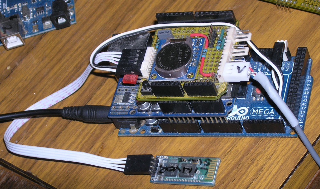
Picture shows a Mega with a store-bought Ethernet shield. By the red reset button, you can see the ICSP connection, which is common to Uno and Mega. The sensor shield carries a clock and started life on a Uno. The SDA and SCL were removed from A4,A5 and wired to a new header at the other end, from whence the black and white pair go to 20,21 on the Mega.
The spare pins are not for switching the service as described before, but for an I2C display.
The plug could conceivably be reconnected to A4,A5 but that is not the intention. Another shield normally sits on top , and the sensor shield is unlikely to sit on a Uno again.
Ok, I'd like to change the subject slightly.
I'm sorry that I'm asking so many questions. I know that I'll start at the very beginning & work my way up.
I know that one can get Arduino modules as well as shields. I've looked at the pictures of the modules & they all have 3 or 4 pins on one side of the board. I suppose that someone has built a project that has both modules & shields. It must be a rats' nest of wires. I know that shields can be stacked one on top of another. How are the shields powered? Do they draw power from the main board or are they powered by USB or a power jack? Likewise, how are the modules powered? Are they powered by USB or do they draw power from the main board or by a power jack? Can modules be mounted on empty shields & be organized that way?
The Arduinos are mainly for experimenting or prototyping. Suppose that someone wants to actually build something from the prototype & wants to merge all of the modules & shields into one PCB. How does one do that?
How are the shields powered?
They can be powered from the Arduino they are plugged into, or they can have their own connector for bringing in power (motor shield for example).
Do they draw power from the main board or are they powered by USB or a power jack?
Both are possible. Depends on the shield.
Likewise, how are the modules powered?
Power from Arduino is possible, external power is possible.
Are they powered by USB or do they draw power from the main board or by a power jack?
Both are possible.
Can modules be mounted on empty shields & be organized that way?
Yes.
Suppose that someone wants to actually build something from the prototype & wants to merge all of the modules & shields into one PCB. How does one do that?
Hire an engineer to merge it all together. I do this regularly for folks.If you have a working prototype to start from that makes it a lot easier. If I have to guess at your intentions and create the design as we go, that takes longer.
Macnerd:
I suppose that someone has built a project that has both modules & shields. It must be a rats' nest of wires.
The pic above shows a module on a shield and another connected by ribbon cable. Yes, there is a bit of a rat's nest, but yoiu can't see it.
In this case, the modules get power off the shield, which gets it off the Mega.
How are the shields powered? Do they draw power from the main board or are they powered by USB or a power jack? Likewise, how are the modules powered?
Shields are typically powered off the main board. Ethernet shields are power-hungry and are supplied off the Vin pin via their own regulators. My GSM shield is worse and has to fed with 5v via its own jack. It appears that that will power the whole stack, but I'm about to ask how.
Can modules be mounted on empty shields & be organized that way?
See pic above. The shield was originally empty.
The Arduinos are mainly for experimenting or prototyping. Suppose that someone wants to actually build something from the prototype & wants to merge all of the modules & shields into one PCB. How does one do that?
By designing a PCB that has all the relevant components and none of the irrelevant components. Components can include modules.