Input, Output, and Setpoint are pointers to the variables holding these values.
Kp, Ki, and Kd are the PID proportional, integral, and derivative gains.
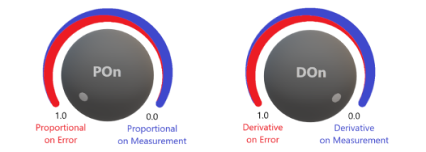
POn is the Proportional on Error weighting value (0.0-1.0). This controls the mix of Proportional on Error (PonE) and Proportional on Measurement (PonM) that's used in the compute algorithm. Note that POn controls the PonE amount, where the remainder (1-PonE) is the PonM amount. Also, the default POn (if not specified) is 0 (100% PonM, 0% PonE).
ControllerDirection Either DIRECT or REVERSE determines which direction the output will move for a given error. DIRECT is most common.
The QuickPID library should soon be available in the Library Manager (request has been made).
Included is an example using an RC filter. With this, AutoTune takes about 12-sec to determine critical gain, period and tuning parameters, then apply and use Kp, Ki and Kd in the sketch ...
New version 2.2.0 has enhanced AutoTune, 8 tuning rules to choose from and new GetKu() and GetTu() functions to display ultimate gain and period. There's now the opportunity to automatically set the sample period based on the Tu determined by AutoTune. Use the updated AutoTune RC Filter example for experimentation.
This auto tuner runs very fast ... it only takes a bit longer than 2 x Tu.
replaced defines with enumerated types and inline functions
Controller Action
If a positive error increases the controller’s output, the controller is said to be direct acting (i.e. heating process). When a positive error decreases the controller’s output, the controller is said to be reverse acting (i.e. cooling process). Since the PWM and ADC peripherals on microcontrollers only operate with positive values, QuickPID only uses positive values for Input, Output and Setpoint. When the controller is set to REVERSE acting, the sign of the error and dInput (derivative of Input) is internally changed. All operating ranges and limits remain the same. To simulate a REVERSE acting process from a process that’s DIRECT acting, the Input value needs to be “flipped”. That is, if your reading from a 10-bit ADC with 0-1023 range, the input value used is (1023 - reading). See the example AutoTune_RC_Filter.ino for details.
I'm trying to use this library to control a line follower.
I'm having an issue with getting the library to behave properly. With Kp = 1, Ki = 0, Kd = 0, I cannot get the controller to maintain a steady output. With a steady error, the output winds up to the output limit, despite having zero ki.
This also appears to be an issue with the original PID library that you started from. I find it hard to believe that I'm the only one who sees this, so what am I missing?
You're right that there's some windup with Kp which seems to provide a beneficial effect (better response to step change of setpoint) for PID or PI controllers. Note that the windup reduces to zero as the error approaches zero, so it doesn't directly cause oscillations or overshoot issues. I may need to re-visit the algorithm and do more testing for P or PD controllers.
After searching "Arduino PID line follower", I haven't found any that use the Arduino PID library ... they all use their own implementation usually of a PD controller.
This example looks promising, they have the source code in the first comment if you expand it.
Resolved Kp windup as noted in issue#6 on GitHub (reply#8 here). Algorithm reverts to upstream library, but with fixed point math option and newer controller direction method maintained.
Updated AutoTune examples and documentation.
Default AutoTune outputStep value in examples (and documentation) is now 5.
Removed fixed point calculations as the speed benefit was very minimal.
Prevent integral windup if output exceeds limits.
Added the following new functions that return the P, I and D terms of the calculation. Now you can get access to all the internal terms for diagnostics, plotting or use in your code ...
    float GetPeTerm();     // proportional on error component of output
    float GetPmTerm();     // proportional on measurement component of output
    float GetIterm();      // integral component of output
    float GetDterm();      // derivative component of output
Added TIMER mode which is used when the PID compute is called by an external timer function or ISR. In this mode, the timer function and SetSampleTimeUs use the same time period value. The PID compute and timer will always remain in sync because the sample time variable and calculations remain constant.
POn controls the mix of Proportional on Error to Proportional on Measurement. Range is 0.0-1.0, default = 1.0
DOn controls the mix of Derivative on Error to Derivative on Measurement. Range is 0.0-1.0, default = 0.0
Derivative Kick:
After looking through Derivative Kick topic in the excellent blog by Brett Beauregard, I was wondering how much difference can be seen when comparing the input plots for derivative on error with the default derivative on measurement method.
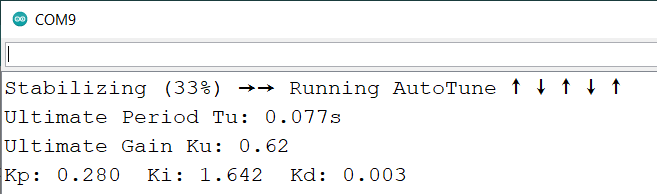
For the test, I used an UNO I have setup with pin 3 PWM output → RC filter (100µF/10K) → input A0. Running AutoTune gave the following results for tuning parameters:
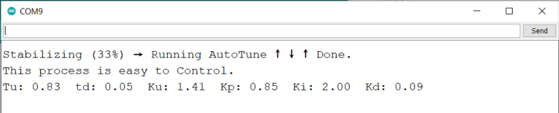
Stabilizing → AutoTune → t0 → t1 → t2 → t3 → done. This process is easy to control. Tu: 0.23 td: 0.01 Ku: 5.73 Kp: 3.44 Ki: 4.34 Kd: 0.10
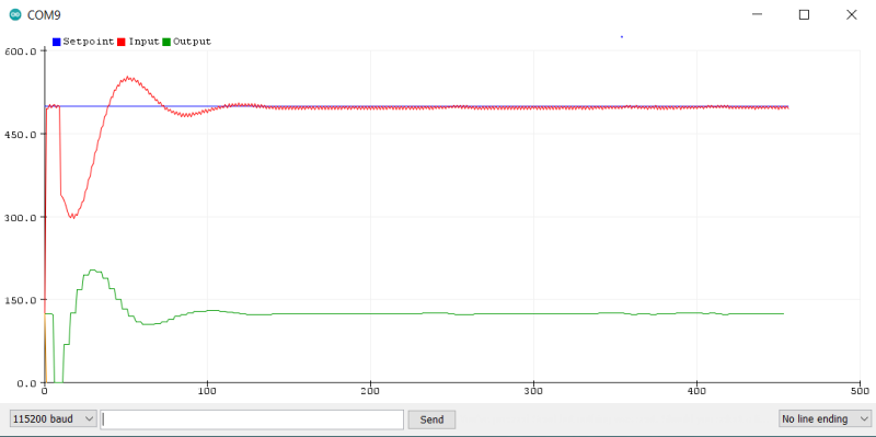
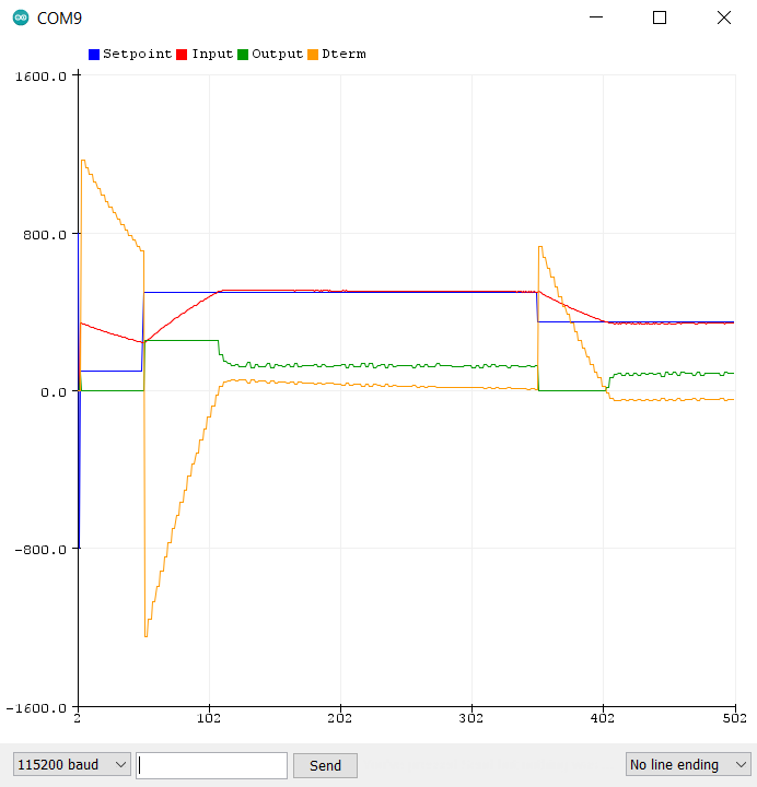
Plot results using ZIEGLER_NICHOLS_PID tuning rule:
Derivative on Measurement: dTerm = kd * dInput;
Derivative on Error: dTerm = -(kd * error);
On this system, the Derivative on Error plot shows a significant improvement on the input overshoot (red trace) and the output (green trace) seems less noisy even when accounting for the increased scaling. No output spikes can be seen but that's probably due to the auto-tuned kp, ki and kd gains that are used.