Can you please post a copy of your circuit, a picture of a hand drawn circuit in jpg, png?
Hand drawn and photographed is perfectly acceptable.
Please include ALL hardware, power supplies, component names and pin labels.
Forget all the fancy colours, if you like use red and black for 5v and gnd, but do the rest in black and white.
What are the transistor part numbers and pin labels for example.
Sorry but a clear diagram, makes for easy interpretation.
If you have not drawn a schematic before, them now is a good time to attempt/learn.
Google;
basics of drawing an electronic schematic diagram
What are you powering the Mega from 9V on the DC socket or 12V on the Vin pin?
thanks tom im currently still learning how to make a schematic but the colors are needed based on my teacher to distinguish one another
that diode is one of my solutions to inductive loads because when the fan is just wired directly it would sometimes display gibberish
for the vin pin i didnt really know what the vin for and i dont understand it so i just copied exactly from the video i watched but he used arduino nano from that and he doesnt have an adapter for the arduino but for me i used both one for the arduino and one from the vin idk if that would cause a problem
what i did is basically the 3 gnd of the buttons are connected to ground and the 5v are connected to a 220 resistor each and then connected to the positive then all those buttons have each pin for the arduino
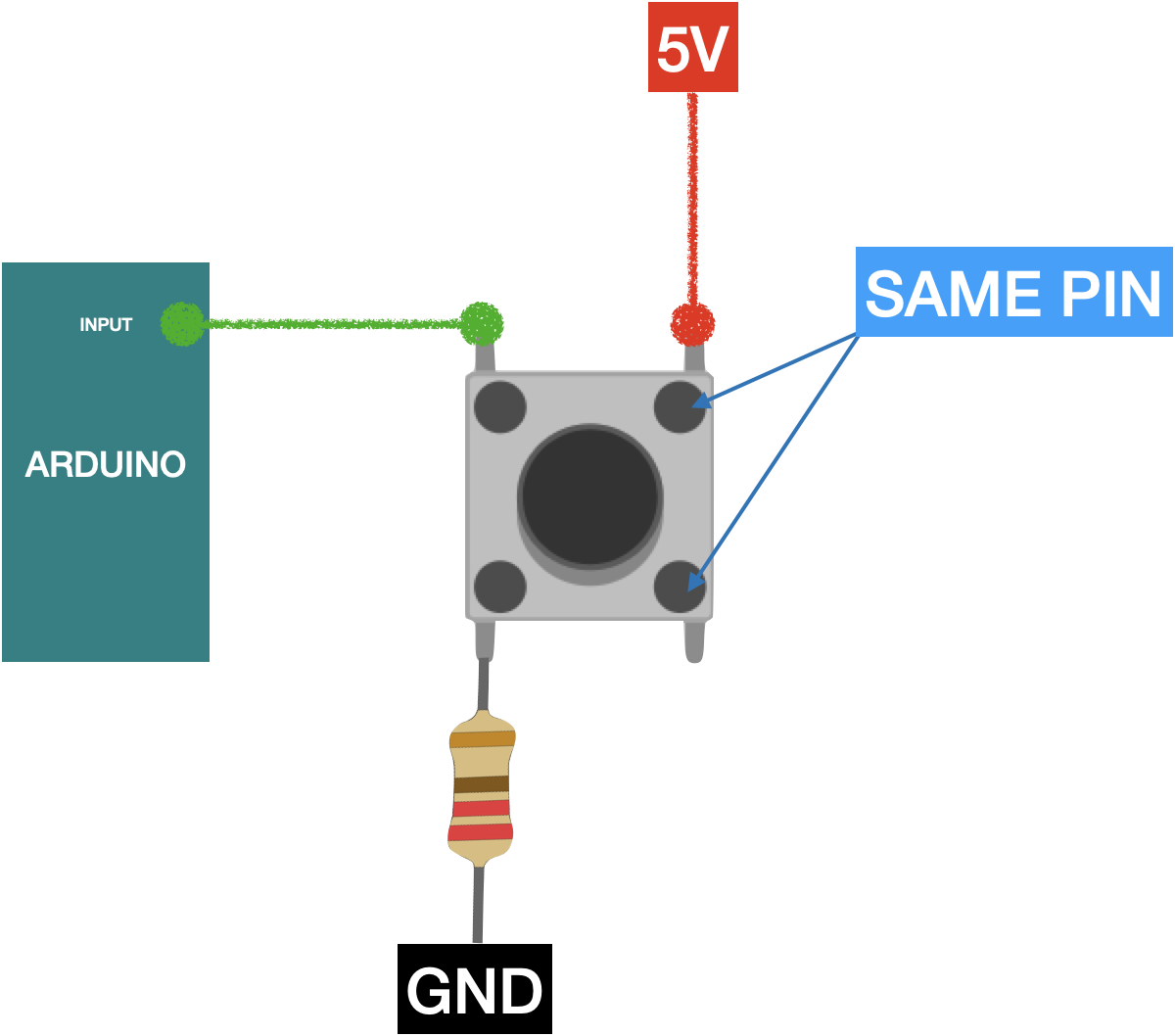
when you have 4 pins on your push button, you really have only 2 different ones. Internally they are connected. So if you want to be sure to include the switch in your circuit and not make use the same pin, you wire diagonally across the button and this way you are sure to not have an issue. (unless you really want to use the same pin).
we would typically not use a pull-down circuit with an extra resistor and wire 5V to the button (risk of short circuit if things go wrong). It's better to connect to GND and use a pullup. see https://docs.arduino.cc/tutorials/generic/digital-input-pullup/
in my circuit the one connected to arduino is in the same line with the 220 and negative then the opposite is connected to the positive and the connection is empty