I'm working on a project with my uncle - he wants to use an Arduino to read an input voltage and if the voltage drops or raises beyond a pre-defined threshold then the Arduino would do A (voltage drop) or B (voltage raise).
The issue is that the voltage we need to monitor is US line voltage (120 volts) and I'm not sure how to approach the problem. Any thoughts on the feasibility and/or possible solutions?
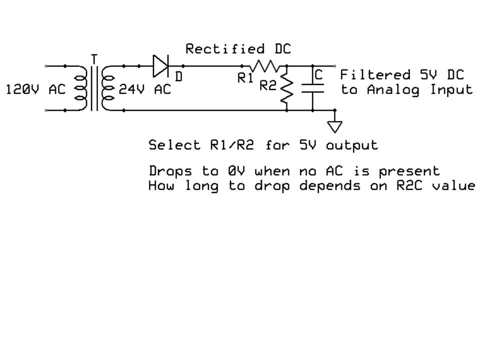
I did look at the link James C45 give you. I simply don't like the circuit. Look simple... yes... Is it going to work ? That, I simply don't know. I did not test the circuit, yet ... And with no protection - like a zener diode at the analog input to make sure it is not going over 5 V or under 0.
I build my monitor using a transformer to reduce the volatge input. ( my circuit use about 10 Vac at the secondary ), you can use a low voltage wall power adapter ( wall wart ), took it apart and you have just a transformer.
My circuit use op-amps, a input resistors network to reduce the voltage to about 3 V ac. The circuit is a peak detector and a buffer. My reference is : "Op-Amps and Linear Integrated Circuit, second edition, by Ramakant A. Gayakwad"
The output have a zener diode for protection, the signal is at 3 V dc ==> 120 Vac rms. And when the Arduino ADC read this voltage, you have a value of 614. As long the voltage at Avref is 5, but in most case, it is not. So you measured it, you place in the code, and you measure the Main AC - 120 with a DMM at AC mode. Mark that reading. Measure the output and mark that reading. Calculated the ratio and place in the code.
Program you code to take into account the ADC value that represent your AC measurment.
code your Arduino to do what you want when the value go up or down.
If you have experience in electronics, you will have no problem doing my circuit. The op-amp need a + side and a - side and the Arduino need 5 V for power or use the + side to power the Arduino via 5 V regulator. And ground properly.
You power up the circuit in this sequence : Arduino , op-amp circuit and the ac in. If you do not do in the proper order, you may damage the circuit and the Arduino. To power down : AC , op-amp and the Arduino
"The ADC is optimized for analog signals with an output impedance of approximately 10 k? or
less. If such a source is used, the sampling time will be negligible. If a source with higher impedance
is used, the sampling time will depend on how long time the source needs to charge the
S/H capacitor, with can vary widely. The user is recommended to only use low impedance
sources with slowly varying signals, since this minimizes the required charge transfer to the S/H
capacitor.
Signal components higher than the Nyquist frequency (fADC/2) should not be present for either
kind of channels, to avoid distortion from unpredictable signal convolution. The user is advised
to remove high frequency components with a low-pass filter before applying the signals as
inputs to the ADC."
I looked at several datasheets, all show the same "1..100Kohm" input resistance.
Sorry to dig up an old thread, but I am also doing something similar (albeit with an MSP430 for a class project). I have a setup that is similar to CrossRoads, but instead of reading across a capacitor, I read across a reverse biased 3v zener diode. Anyways, I am hoping to use a digital input pin on the MSP430 to detect the square wave (fewer instructions, less power). However, when I want to read the rectified 3V signal, it needs to be referenced against the ground of the transformer (but I would expect that the MSP430 compares the digital IO pin against its own ground). Is there a good way to set up the MSP430 (or any MCU for that matter) so that I can compare a signal with a different ground from the MCU on a digital IO pin, or should I just use the ADC and set V-ref to the transformer ground?