Hi,
I've been banging my head for a few days and I can't find a solution...
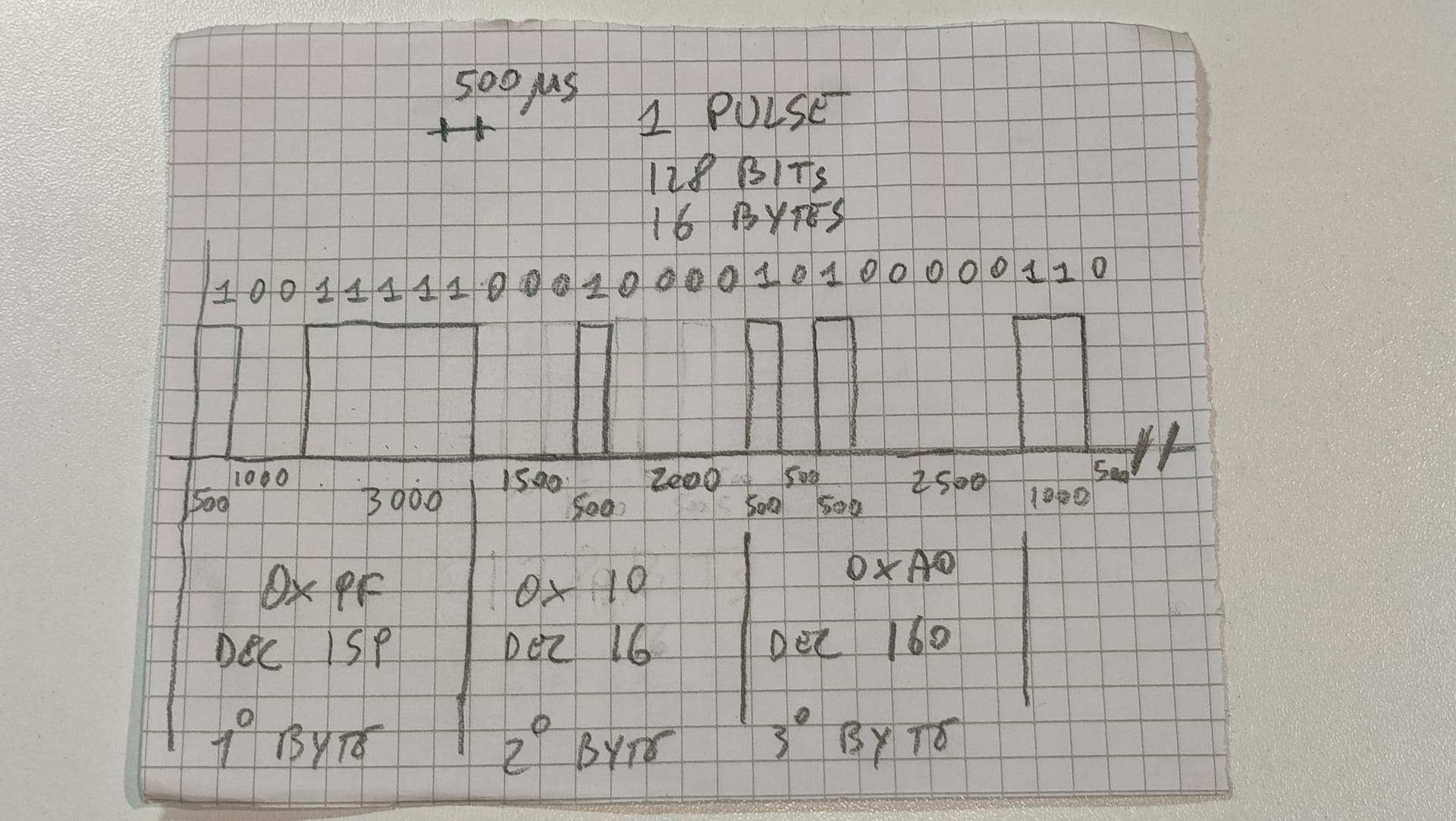
I have a train of 128 consecutive pulses of 500 microseconds each (16 bytes) and they are not spaced between one pulse and the other; I've tried various techniques to try to decode it, but I find it difficult to recognize the individual pulses when there are multiple consecutive bits at one or zero...
I've also tried the interrupt technique, but with consecutive bits since there is no change of edge it doesn't work. I would just need a tip for the logic to follow, I think I'm complicating things more than they perhaps are...
Thanks in advance
Hi, @saver22
Where are the pulses coming from?
What format
What baud rate?
Tom... ![]()
![]()
![]()
![]()
Can you draw or show us a visualisation of two sequential pulse bursts. (scope maybe)
If you can add timing and notes, so we’ll understand it quicker.
Hi,
the pulses come from an RF transmitter that has its receiver integrated into a device; I would like to intercept the data to integrate it into my system. The protocol is proprietary, I can't trace it back to a standard, but the first byte identifies the device, the second indicates how many bytes the data is made up of and the last byte indicates the checksum. Therefore, out of 16 bytes there are 13 bytes of data + 3 of service...
That’s only thre bytes unfortunately,
From what you’re saying,there’s no sync gap or pause between each packet of bytes, so you have to be sure of the timing, or maybe there’s a separate clear & clock. like used with a chain of shift registers.
HI,
What part of the data stream you have drawn, changes?
What part of the data stream you have drawn, does not change?
What does this data stream control?
Tom... ![]()
![]()
![]()
![]()
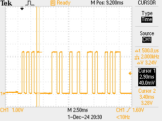
What kind of measurement-equipment did you use to find about the pulses?
digitale storage oscilloscope?
24 MHz 8 ch logic analyser?
sampling an IO-pin at highest possible frequency?
using a small testcode with attachInterrupt(CHANGE ) which stores time-stamps each time the interrupt is invoked?
Looking up some kind of datasheet?
I am astonished that you can tell there are 128 pulses = 16 bytes
What makes you sure that there are 128 pulses if two following zeros are just a flat lower line?
Do you see the values as dezimal or hexadecimal or ASCII-coded numbers of all 16 bytes in this device ?
This would be a way to make sure that your assumptions about the signal train are correct.
Do you have any kind of datasheet or manual that explains the pulsetrain?
How many different signal-trains did you observe?
If there are only 3 to 5 you could use the timing-pattern of long/short pulses to identify which "data" this is
byte 1 is the length.
Is this always the same length of 16 bytes?
What do byte 2-16 represent?
- a text message?
- measuring data? (of what? how many digits?)
The more information that you can provide the better suggestions can be made
If there really is no syncing-gap and no syncing "special-pulse"
but the first byte is the length and this length is always the same you could use
this first byte for syncing.
Again: what measurement-equipment did you use to analyse the signal-train?
Are you sure that in the first byte all 8 bits are used to code the length?
It might be that the first 2 to 4 bits are used for synchronising.
Though with this less information this is hard to tell.
guessing that the pulses represent binary data where each bit is represented by the presence/absence of a pulse during a bit period. (another possibility is that each pulse width represents some data)
this approach is commonly used with serial data using a UART. without a separate clock signal, all timing is relative to some clock on the receiver. Because the clock may not be perfectly synchronized only a limited # of bits can be transmitted.
UARTS typically transmit no more than 8 bits with a START bit that is opposite the idle condition of the signal and a STOP bit that is the idle condition, guaranteeing that the START bit can be recognized.
a typical UART implementation recognizes the START bit transition, then waits one half bit period before capturing bits every bit period.
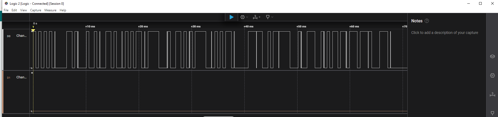
Update...
I attach the capture of a logic analyzer where you can actually see the entire sequence of 128 bits and in fact there is a pulse that indicates the end of each byte (72-76µs) that I was missing...
The first byte is fixed and identifies the device (and could be taken to synchronize), the second is the length of the data bytes that it will transmit (which could also be less than 13) and the last is a CRC.
In the capture the transmitted bytes are: AA,0D,12,34,56,78,9A,BC,56,07,CB,F1,39,5B,77,8E and the pulse is about 500µs (I saw that in the case of consecutive pulses of the same state the duration of each pulse can even reach 540-550µs each).
I hope this time I have given you all the information possible and I apologize for not having done so before.
Saver

if the first byte is the sequence of 4 wide, 10101010b, and one narrow pulse, it looks like each byte is ~5 msec, not 75usec.
that narrow pulse is more likely a start sequence with an equally narrow zero bit preceeding it, to distinguish it from the last data bit and followed by an equally narrow zero pulse immediately followed by a 8 bits of data. you can see this in the 7th byte, 0x9A, otherwise how do you detect the start of a byte such as 0x70 or 0x01
Guessing that each bit is 1 ~0.5msec, but the start sequence is smaller
Aha.
So a first approach could be to detect each rising and each falling edge
taking time-stamps on each edge.
Then calculating the time the pulse lasted high.
timestamp-of-falling-edge - timestamp-of-rising-edge
If it is just 72 to 76 microseconds you can conclude: end of byte-pulse

Then starting to sample the bits in the middle of the bit-time by using a timer-interrupt.
You should measure how many microseconds are there between falling.edge of the 75 µsec-pulse (the end-of-byte-pulse) and the rising-edge of bit 7 if this bit has value 1
you should measure the high-time of a lot of bits to obtain an average-value
How many microseconds are there from rising-edge of the end-of-byte-pulse
to rising edge of the
next end-of-byte-pulse?
With these timing-data you can setup a timer-interrupt-routine and start the timer at the right time for sampling the bit-values
ignoring the 75uSec start/end pulse the sequence {0xAA,0x0d,0x12,0x34,0x56} would look like (500uSec pulse width)
this may give you some ideas (for a ESP32)
// ESP32 - measure pulse width and rising edge-to-edge time using timer1 pins 16 and 17

// updated for Arduino ESP32 core 3.0 see
// https://docs.espressif.com/projects/arduino-esp32/en/latest/api/timer.html

// note using hw_timer_t or micros() give similar values
hw_timer_t *Timer1_Cfg = NULL;  // timer object

// arrays to hold pulse timing data
uint64_t risingTime[500] = { 0 }, fallingTime[500] = { 0 };
int riseIndex = 0, fallIndex = 0;
long int millisTimeOut=0;
// rising edge interrupt read time in uSec
void IRAM_ATTR rising() {
  if(riseIndex >= sizeof(risingTime)) return;
  risingTime[riseIndex++] = timerReadMicros(Timer1_Cfg);
  millisTimeOut=millis();
}

// falling edge interrupt read time in uSec
void IRAM_ATTR falling() {
  if(fallIndex >= sizeof(fallingTime)) return;
  fallingTime[fallIndex++] = (timerReadMicros(Timer1_Cfg));
}

void setup() {
  Serial.begin(115200);
  delay(1000);
  Serial.printf("\n\nESP32 measure pins 16 and 17 pulse information \n");
  //Timer1_Cfg = timerBegin(0, 80, true);           // API 2.x setup timer for 1uSec
  if ((Timer1_Cfg = timerBegin(1000000)) == NULL)  // API 3.0 setup timer for 1uSec
    Serial.println("timerBegin Failed!!");
  Serial.print("timerBegin() OK frequenmcy ");
  Serial.println(timerGetFrequency(Timer1_Cfg));
  //  setup interrput routines - connect signal to pins 16 and 17
  attachInterrupt(digitalPinToGPIONumber(16), rising, RISING);    // detect rising edge on pin 16
  attachInterrupt(digitalPinToGPIONumber(17), falling, FALLING);  // detect falling edge on pin 17
  Serial.println("displaying results");
}

void loop() {
  // if 2 seconds have elapsed since last redaing print results
  if(riseIndex > 0 && millis()-millisTimeOut>2000) {//timerReadMicros(Timer1_Cfg)-risingTime[riseIndex-1]>2e6) {
    for (int i = 0; i < riseIndex; i++) {
      Serial.printf("rise %lld fall %lld period %lld\n",
                    risingTime[i], fallingTime[i], fallingTime[i] - risingTime[i]);
      Serial.printf("fall %lld rise %lld period %lld\n",
                    fallingTime[i], risingTime[i + 1], risingTime[i + 1] - fallingTime[i]);
    }
    Serial.print("\npulse width counters ");
    for (int i = 0; i < riseIndex; i++) {
      // calculate pulse timing - add 100 in case readings are less than 500uSec
      uint64_t bit = fallingTime[i] - risingTime[i] + 100;
      Serial.print(bit / 500);
      if (i + 1 >= riseIndex) break;
      bit = risingTime[i + 1] - fallingTime[i] + 100;
      Serial.print(bit / 500);
    }
    Serial.print("\nbit pattern ");
    for (int i = 0; i < riseIndex; i++) {
      uint64_t bit = fallingTime[i] - risingTime[i] + 100;
      for (int j = 0; j < bit / 500; j++)
        Serial.print('1');
      if (i + 1 >= riseIndex) break;
      bit = risingTime[i + 1] - fallingTime[i] + 100;
      for (int j = 0; j < bit / 500; j++)
        Serial.print('0');
    }
    Serial.println("\n");
    riseIndex=fallIndex=0;
  }
}
pulse sequences give serial monitor output
ESP32 measure pins 16 and 17 pulse information
timerBegin() OK frequenmcy 1000000
displaying results
rise 2939846 fall 2940328 period 482
fall 2940328 rise 2940826 period 498
rise 2940826 fall 2941326 period 500
fall 2941326 rise 2941826 period 500
rise 2941826 fall 2942326 period 500
fall 2942326 rise 2942826 period 500
rise 2942826 fall 2943326 period 500
fall 2943326 rise 2945826 period 2500
rise 2945826 fall 2946826 period 1000
fall 2946826 rise 2947325 period 499
rise 2947325 fall 2947826 period 501
fall 2947826 rise 2949326 period 1500
rise 2949326 fall 2949826 period 500
fall 2949826 rise 2950826 period 1000
rise 2950826 fall 2951326 period 500
fall 2951326 rise 2952826 period 1500
rise 2952826 fall 2953826 period 1000
fall 2953826 rise 2954325 period 499
rise 2954325 fall 2954826 period 501
fall 2954826 rise 2956326 period 1500
rise 2956326 fall 2956825 period 499
fall 2956825 rise 2957326 period 501
rise 2957326 fall 2957826 period 500
fall 2957826 rise 2958326 period 500
rise 2958326 fall 2959326 period 1000
fall 2959326 rise 0 period -2959326

pulse width counters 1111111521131213211311112
bit pattern 101010100000110100010010001101000101011

rise 17666823 fall 17667312 period 489
fall 17667312 rise 17667809 period 497
rise 17667809 fall 17668309 period 500
fall 17668309 rise 17668809 period 500
rise 17668809 fall 17669309 period 500
fall 17669309 rise 17669809 period 500
rise 17669809 fall 17670309 period 500
fall 17670309 rise 17672809 period 2500
rise 17672809 fall 17673809 period 1000
fall 17673809 rise 17674309 period 500
rise 17674309 fall 17674809 period 500
fall 17674809 rise 17676309 period 1500
rise 17676309 fall 17676809 period 500
fall 17676809 rise 17677809 period 1000
rise 17677809 fall 17678309 period 500
fall 17678309 rise 17679809 period 1500
rise 17679809 fall 17680809 period 1000
fall 17680809 rise 17681309 period 500
rise 17681309 fall 17681809 period 500
fall 17681809 rise 17683309 period 1500
rise 17683309 fall 17683809 period 500
fall 17683809 rise 17684309 period 500
rise 17684309 fall 17684809 period 500
fall 17684809 rise 17685309 period 500
rise 17685309 fall 17686309 period 1000
fall 17686309 rise 0 period -17686309

pulse width counters 1111111521131213211311112
bit pattern 101010100000110100010010001101000101011

rise 41859928 fall 41860418 period 490
fall 41860418 rise 41860916 period 498
rise 41860916 fall 41861416 period 500
fall 41861416 rise 41861916 period 500
rise 41861916 fall 41862416 period 500
fall 41862416 rise 41862916 period 500
rise 41862916 fall 41863415 period 499
fall 41863415 rise 41865916 period 2501
rise 41865916 fall 41866915 period 999
fall 41866915 rise 41867415 period 500
rise 41867415 fall 41867915 period 500
fall 41867915 rise 41869416 period 1501
rise 41869416 fall 41869915 period 499
fall 41869915 rise 41870915 period 1000
rise 41870915 fall 41871416 period 501
fall 41871416 rise 41872915 period 1499
rise 41872915 fall 41873915 period 1000
fall 41873915 rise 41874415 period 500
rise 41874415 fall 41874915 period 500
fall 41874915 rise 41876415 period 1500
rise 41876415 fall 41876915 period 500
fall 41876915 rise 41877415 period 500
rise 41877415 fall 41877915 period 500
fall 41877915 rise 41878415 period 500
rise 41878415 fall 41879415 period 1000
fall 41879415 rise 0 period -41879415

pulse width counters 1111111521131213211311112
bit pattern 101010100000110100010010001101000101011
may give you some ideas
did you ever determine the precise timing of the stop/start pulse(s)
try running the program of post 13 may give you some idea
if I run it with the following test data

it gives (times in uSec)
rise 5207049 fall 5207561 period 512
fall 5207561 rise 5208079 period 518
rise 5208079 fall 5208598 period 519
fall 5208598 rise 5209115 period 517
rise 5209115 fall 5209632 period 517
fall 5209632 rise 5210149 period 517
rise 5210149 fall 5210667 period 518
fall 5210667 rise 5211192 period 525
rise 5211192 fall 5211294 period 102

fall 5211294 rise 5213534 period 2240
rise 5213534 fall 5214568 period 1034
fall 5214568 rise 5215086 period 518
rise 5215086 fall 5215606 period 520
fall 5215606 rise 5215708 period 102
rise 5215708 fall 5215877 period 169
the stop/start pulse is approximately 100uSec wide
how often do you get the 16byte sequence? every minute? continuous?
Sorry but I'm away for work and for a while I can't follow the project... as soon as I can I'll take inspiration from what you suggested, for now thanks!
Here I am again!
I have taken up the topic again and I have arrived very well.
Following your advice and taking inspiration from the excellent (complete) base posted by @horace and understanding the mechanism he has adopted, I have modified the code to make it work with the reduced capabilities of Arduino compared to an ESP and I have managed to capture and decode the entire train of pulses, measuring the time intervals between the edges with very low measurement errors, we are talking about ±4/6 µs compared to the time detected by the logic analyzer; I then grouped the bits into bytes obtaining the sequence of bytes transmitted.
This technique is very simple and sophisticated at the same time, and allows you to analyze any type of signal that is present on the pin, regardless of the protocol used: once the times are decoded you can do whatever you want...
To then verify the stability of reading with long codes, I generated a "sample" code with a shorter and longer pulse (up to 30µs compared to the 500µs of transmission) and the reading is always OK without any loss, that is, the transmitted code can have a tolerance of up to ±6% compared to the width of the expected pulse.
I attach the code that is more enriched than what is needed but I see it as a reference to draw from for future applications.
I would say that this is a great starting point for numerous projects and thanks again to everyone for the collaborative support.
Saver
OUTPUT on serial monitor
Arduino measure single pin pulse information
Initialization completed, measuring in progress...
rise 4874280 fall 4874752 period ▲ 472
fall 4874752 rise 4875228 period ▼ 476
rise 4875228 fall 4875704 period ▲ 476
fall 4875704 rise 4876180 period ▼ 476
rise 4876180 fall 4876656 period ▲ 476
fall 4876656 rise 4877132 period ▼ 476
rise 4877132 fall 4877608 period ▲ 476
fall 4877608 rise 4878092 period ▼ 484
rise 4878092 fall 4878164 period ▲ 72
fall 4878164 rise 4880612 period ▼ 2448
rise 4880612 fall 4881564 period ▲ 952
fall 4881564 rise 4882052 period ▼ 488
rise 4882052 fall 4882120 period ▲ 68
fall 4882120 rise 4883620 period ▼ 1500
rise 4883620 fall 4884092 period ▲ 472
fall 4884092 rise 4885044 period ▼ 952
rise 4885044 fall 4885520 period ▲ 476
fall 4885520 rise 4886004 period ▼ 484
rise 4886004 fall 4886076 period ▲ 72
fall 4886076 rise 4887100 period ▼ 1024
rise 4887100 fall 4888052 period ▲ 952
fall 4888052 rise 4888628 period ▼ 576
rise 4888628 fall 4889100 period ▲ 472
fall 4889100 rise 4890060 period ▼ 960
rise 4890060 fall 4890132 period ▲ 72
fall 4890132 rise 4890684 period ▼ 552
rise 4890684 fall 4891156 period ▲ 472
fall 4891156 rise 4891632 period ▼ 476
rise 4891632 fall 4892108 period ▲ 476
fall 4892108 rise 4892584 period ▼ 476
rise 4892584 fall 4893536 period ▲ 952
fall 4893536 rise 4894020 period ▼ 484
rise 4894020 fall 4894092 period ▲ 72
fall 4894092 rise 4894640 period ▼ 548
rise 4894640 fall 4896544 period ▲ 1904
fall 4896544 rise 4897976 period ▼ 1432
rise 4897976 fall 4898048 period ▲ 72
fall 4898048 rise 4898120 period ▼ 72
rise 4898120 fall 4898596 period ▲ 476
fall 4898596 rise 4899548 period ▼ 952
rise 4899548 fall 4900496 period ▲ 948
fall 4900496 rise 4900972 period ▼ 476
rise 4900972 fall 4901448 period ▲ 476
fall 4901448 rise 4901932 period ▼ 484
rise 4901932 fall 4902004 period ▲ 72
fall 4902004 rise 4902076 period ▼ 72
rise 4902076 fall 4902552 period ▲ 476
fall 4902552 rise 4903028 period ▼ 476
rise 4903028 fall 4905028 period ▲ 2000
fall 4905028 rise 4905988 period ▼ 960
rise 4905988 fall 4906060 period ▲ 72
fall 4906060 rise 4906608 period ▼ 548
rise 4906608 fall 4907560 period ▲ 952
fall 4907560 rise 4908036 period ▼ 476
rise 4908036 fall 4908508 period ▲ 472
fall 4908508 rise 4908984 period ▼ 476
rise 4908984 fall 4909460 period ▲ 476
fall 4909460 rise 4909948 period ▼ 488
rise 4909948 fall 4910016 period ▲ 68
Bit pattern split into bytes:
#1 10101010 (DEC:170, HEX:AA)
#1 110 (DEC:6, HEX:6)
#2 10010 (DEC:18, HEX:12)
#2 110100 (DEC:52, HEX:34)
#2 1010110 (DEC:86, HEX:56)
#3 1111000 (DEC:120, HEX:78)
#3 10011010 (DEC:154, HEX:9A)
#4 10111100 (DEC:188, HEX:BC)
#4 1101010 (DEC:106, HEX:6A)
/*
###############################################################
07/12/2024
thorlab.0125.eu

      Supported by Arduino forum, special thanks to @horace
          https://forum.arduino.cc/u/horace/summary

                   Pulse train decoding
               Reading errors of ± 4/6 µs...
###############################################################
*/

// Global variables
#define DATA_PIN 2                               // PIN input
#define SERIAL_DATA_SPEED 115200                 // serial speed for serial monitor
#define WIDE_PULSE 500                           // wide pulse in µs, max. tolerance +/-6%
#define NUMBER_OF_PULSES 125                     // maximum pulses to receive

unsigned long risingTime[NUMBER_OF_PULSES] = {0}, fallingTime[NUMBER_OF_PULSES] = {0};
int riseIndex = 0, fallIndex = 0;
unsigned long millisTimeOut = 0;


// Unique ISR to handle both RISING and FALLING
void handleChange() {
  if (digitalRead(DATA_PIN) == HIGH) {
    // Rising front
    if (riseIndex < sizeof(risingTime) / sizeof(risingTime[0])) {
      risingTime[riseIndex++] = micros();
      millisTimeOut = millis();          // Update timeout
    }
  } else {
    // Falling front
    if (fallIndex < sizeof(fallingTime) / sizeof(fallingTime[0])) {
      fallingTime[fallIndex++] = micros();
    }
  }
}


void setup() {
  Serial.begin(SERIAL_DATA_SPEED);
  delay(500);                                 // Wait for the serial monitor to be ready

  Serial.println("\n\nArduino measure single pin pulse information");

  // Configure the pin for the interrupt
  pinMode(DATA_PIN, INPUT_PULLUP);            // Signal pin with pullup resistor

  // Bind interrupt for state changes
  attachInterrupt(digitalPinToInterrupt(DATA_PIN), handleChange, CHANGE);   // interrupt set for PIN state change
  Serial.println("Initialization completed, measuring in progress...");
  Serial.println("==================================================");
}


void loop() {
  // If 100 ms has passed since the last measurement, print the results
  if (riseIndex > 0 && millis() - millisTimeOut > 100) {
    for (int i = 0; i < riseIndex; i++) {
      // Calculate and print the periods between the edges
      Serial.print("rise ");
      Serial.print(risingTime[i]);
      Serial.print(" fall ");
      Serial.print(fallingTime[i]);
      Serial.print(" period ▲ ");
      Serial.println(fallingTime[i] - risingTime[i]);

      if (i + 1 < riseIndex) {
        Serial.print("fall ");
        Serial.print(fallingTime[i]);
        Serial.print(" rise ");
        Serial.print(risingTime[i + 1]);
        Serial.print(" period ▼ ");
        Serial.println(risingTime[i + 1] - fallingTime[i]);
      }
    }

    // Calculate and print patterns in binary with progressive, decimal and hexadecimal
    Serial.println("\nBit pattern split into bytes:");
    Serial.println("=============================");
    int bitIndex = 0;
    byte currentByte = 0;

    for (int i = 0; i < riseIndex; i++) {
      unsigned long bit = fallingTime[i] - risingTime[i] + 100;
      for (int j = 0; j < bit / WIDE_PULSE; j++) {
        // Add '1' to the current byte
        currentByte = (currentByte << 1) | 1;
        bitIndex++;

        // If the byte is complete (8 bits), I print it.
        if (bitIndex == 8) {
          Serial.print("#");
          Serial.print(i / 8 + 1);                  // Progressive number
          Serial.print(" ");
          Serial.print(String(currentByte, BIN));   // Print byte in binary
          Serial.print(" (DEC:");
          Serial.print(currentByte, DEC);           // Decimal
          Serial.print(", HEX:");
          Serial.print(currentByte, HEX);           // Hexadecimal
          Serial.println(")");

          // Reset the current byte and index
          currentByte = 0;
          bitIndex = 0;
        }
      }

      if (i + 1 >= riseIndex) break;

      bit = risingTime[i + 1] - fallingTime[i] + 100;
      for (int j = 0; j < bit / WIDE_PULSE; j++) {
        // Add '0' to the current byte
        currentByte = (currentByte << 1);
        bitIndex++;

        // If the byte is complete (8 bits), print it
        if (bitIndex == 8) {
          Serial.print("#");
          Serial.print(i / 8 + 1);                  // Progressive number
          Serial.print(" ");
          Serial.print(String(currentByte, BIN));   // Print byte in binary
          Serial.print(" (DEC:");
          Serial.print(currentByte, DEC);           // Decimal
          Serial.print(", HEX:");
          Serial.print(currentByte, HEX);           // Hexadecimal
          Serial.println(")");

          // Reset the current byte and index
          currentByte = 0;
          bitIndex = 0;
        }
      }
    }

    // If there are any incomplete bits left, print them as a final byte.
    if (bitIndex > 0) {
      currentByte <<= (8 - bitIndex);           // Pad the byte with zeros on the right
      Serial.print("#");
      Serial.print((riseIndex + 7) / 8);        // Progressive number
      Serial.print(" ");
      Serial.print(String(currentByte, BIN));   // Print byte in binary
      Serial.print(" (DEC:");
      Serial.print(currentByte, DEC);           // Decimal
      Serial.print(", HEX:");
      Serial.print(currentByte, HEX);           // Hexadecimal
      Serial.println(")");
    }

    Serial.println("\n");

    // Reset the indexes
    riseIndex = fallIndex = 0;
  }
}
2 Likes
good to heard you solved the problem!
I ran the following test data thru you program (on a ESP32)
0xAA, 0x0d, 0x12, 0x34, 0, 0x56, 0xff, 0x78, 0x9A, 0xBC, 0x56, 0x07, 0XCB, 0XF1
you see I have added a test for 0x00 and 0xFF
the result was
Arduino measure single pin pulse information
Initialization completed, measuring in progress...
==================================================
rise 9432200 fall 9432692 period ? 492
fall 9432692 rise 9433189 period ? 497
rise 9433189 fall 9433687 period ? 498
fall 9433687 rise 9434184 period ? 497
rise 9434184 fall 9434683 period ? 499
fall 9434683 rise 9435180 period ? 497
rise 9435180 fall 9435677 period ? 497
fall 9435677 rise 9436175 period ? 498
rise 9436175 fall 9436251 period ? 76
fall 9436251 rise 9438384 period ? 2133
rise 9438384 fall 9439379 period ? 995
fall 9439379 rise 9439877 period ? 498
rise 9439877 fall 9440375 period ? 498
fall 9440375 rise 9440451 period ? 76
rise 9440451 fall 9440599 period ? 148
fall 9440599 rise 9442093 period ? 1494
rise 9442093 fall 9442591 period ? 498
fall 9442591 rise 9443589 period ? 998
rise 9443589 fall 9444088 period ? 499
fall 9444088 rise 9444590 period ? 502
rise 9444590 fall 9444667 period ? 77
fall 9444667 rise 9445805 period ? 1138
rise 9445805 fall 9446800 period ? 995
fall 9446800 rise 9447298 period ? 498
rise 9447298 fall 9447796 period ? 498
fall 9447796 rise 9448793 period ? 997
rise 9448793 fall 9448870 period ? 77
fall 9448870 rise 9452995 period ? 4125
rise 9452995 fall 9453071 period ? 76
fall 9453071 rise 9453714 period ? 643
rise 9453714 fall 9454212 period ? 498
fall 9454212 rise 9454710 period ? 498
rise 9454710 fall 9455207 period ? 497
fall 9455207 rise 9455705 period ? 498
rise 9455705 fall 9456700 period ? 995
fall 9456700 rise 9457199 period ? 499
rise 9457199 fall 9457275 period ? 76
fall 9457275 rise 9457418 period ? 143
rise 9457418 fall 9461400 period ? 3982
fall 9461400 rise 9461477 period ? 77
rise 9461477 fall 9461625 period ? 148
fall 9461625 rise 9462122 period ? 497
rise 9462122 fall 9464112 period ? 1990
fall 9464112 rise 9465605 period ? 1493
rise 9465605 fall 9465681 period ? 76
fall 9465681 rise 9465825 period ? 144
rise 9465825 fall 9466322 period ? 497
fall 9466322 rise 9467317 period ? 995
rise 9467317 fall 9468311 period ? 994
fall 9468311 rise 9468809 period ? 498
rise 9468809 fall 9469306 period ? 497
fall 9469306 rise 9469804 period ? 498
rise 9469804 fall 9469879 period ? 75
fall 9469879 rise 9470024 period ? 145
rise 9470024 fall 9470521 period ? 497
fall 9470521 rise 9471019 period ? 498
rise 9471019 fall 9473009 period ? 1990
fall 9473009 rise 9474005 period ? 996
rise 9474005 fall 9474082 period ? 77
fall 9474082 rise 9474725 period ? 643
rise 9474725 fall 9475223 period ? 498
fall 9475223 rise 9475721 period ? 498
rise 9475721 fall 9476218 period ? 497
fall 9476218 rise 9476716 period ? 498
rise 9476716 fall 9477711 period ? 995
fall 9477711 rise 9478210 period ? 499
rise 9478210 fall 9478286 period ? 76
fall 9478286 rise 9480919 period ? 2633
rise 9480919 fall 9482413 period ? 1494
fall 9482413 rise 9482488 period ? 75
rise 9482488 fall 9483633 period ? 1145
fall 9483633 rise 9484627 period ? 994
rise 9484627 fall 9485125 period ? 498
fall 9485125 rise 9485622 period ? 497
rise 9485622 fall 9486619 period ? 997
fall 9486619 rise 9486696 period ? 77
rise 9486696 fall 9488828 period ? 2132
fall 9488828 rise 9490321 period ? 1493
rise 9490321 fall 9490818 period ? 497
fall 9490818 rise 9490895 period ? 77
rise 9490895 fall 9490971 period ? 76

Bit pattern split into bytes:
=============================
#1 10101010 (DEC:170, HEX:AA)
#1 1101 (DEC:13, HEX:D)
#2 10010 (DEC:18, HEX:12)
#2 110100 (DEC:52, HEX:34)
#2 0 (DEC:0, HEX:0)
#3 1010110 (DEC:86, HEX:56)
#3 11111111 (DEC:255, HEX:FF)
#3 1111000 (DEC:120, HEX:78)
#4 10011010 (DEC:154, HEX:9A)
#4 10111100 (DEC:188, HEX:BC)
#5 1010110 (DEC:86, HEX:56)
#5 111 (DEC:7, HEX:7)
#5 11001011 (DEC:203, HEX:CB)
#5 11110001 (DEC:241, HEX:F1)
all correct
my version of the code to decode the serial was
// ESP32 - measure pulse width and rising edge-to-edge time using timer1 pins 16 and 17
// https://forum.arduino.cc/t/reading-a-pulse-train/1327585/14

// updated for Arduino ESP32 core 3.0 see
// https://docs.espressif.com/projects/arduino-esp32/en/latest/api/timer.html

// note using hw_timer_t or micros() give similar values
hw_timer_t *Timer1_Cfg = NULL;  // timer object

// arrays to hold pulse timing data
uint64_t risingTime[500] = { 0 }, fallingTime[500] = { 0 };
int riseIndex = 0, fallIndex = 0;
long int millisTimeOut = 0;
// rising edge interrupt read time in uSec
void IRAM_ATTR rising() {
  if (riseIndex >= sizeof(risingTime)) {
    riseIndex = fallIndex = millisTimeOut = 0;
    return;
  }
  risingTime[riseIndex++] = timerReadMicros(Timer1_Cfg);
  millisTimeOut = millis();
}

// falling edge interrupt read time in uSec
void IRAM_ATTR falling() {
  if (fallIndex >= sizeof(fallingTime)) {
    riseIndex = fallIndex = millisTimeOut = 0;
    return;
  }
  fallingTime[fallIndex++] = (timerReadMicros(Timer1_Cfg));
}

void setup() {
  Serial.begin(115200);
  delay(1000);
  Serial.printf("\n\nESP32 measure pins 16 and 17 pulse information \n");
  //Timer1_Cfg = timerBegin(0, 80, true);           // API 2.x setup timer for 1uSec
  if ((Timer1_Cfg = timerBegin(1000000)) == NULL)  // API 3.0 setup timer for 1uSec
    Serial.println("timerBegin Failed!!");
  Serial.print("timerBegin() OK frequenmcy ");
  Serial.println(timerGetFrequency(Timer1_Cfg));
  //  setup interrput routines - connect signal to pins 16 and 17
  attachInterrupt(digitalPinToGPIONumber(16), rising, RISING);    // detect rising edge on pin 16
  attachInterrupt(digitalPinToGPIONumber(17), falling, FALLING);  // detect falling edge on pin 17
  Serial.println("displaying results");
}

byte dataReceived[500];
int dataIndex = 0;

void loop() {
  // if 2 seconds have elapsed since last redaing print results
  if (riseIndex > 0 && millis() - millisTimeOut > 2000) {
    byte datain = 0;
    bool validData = false;
    // loop thru the rise and fall time arrays
    for (int i = 0; i < riseIndex; i++) {

      int count = 0;
      // calculate HIGH pulse width time
      Serial.printf("\n%d rise %lld fall %lld period %lld bits ",
                    i, risingTime[i], fallingTime[i], fallingTime[i] - risingTime[i]);
      uint64_t bit = fallingTime[i] - risingTime[i];
      Serial.printf(" count %d ", count = (int)round(bit / 500.0));
      // found stop BIT (count=0) ?
      if (count) {  // if count is none 0 add bit to datain
        if (count > 10) {
          printf("\nERROR rise i %d bit count %d\n", i, count);
          continue;  // ERROR!
        }
        for (int j = 0; j < count; j++) {
          Serial.print('1');
          datain = (datain << 1) | 1;
          validData = true;
        }
      } else {  // if count is 0 is end of a byte print result
        if (validData)
          Serial.printf(" datain 0x%02X\n", dataReceived[dataIndex++] = datain);
        datain = 0;
        validData = false;
      }
      // calculate LOW pulse width time
      Serial.printf("\nfall %lld rise %lld period %lld bits ",
                    fallingTime[i], risingTime[i + 1], risingTime[i + 1] - fallingTime[i]);
      bit = risingTime[i + 1] - fallingTime[i];
      Serial.printf(" count %d ", count = (int)round(bit / 500.0));
      // found stop BIT (count=0) ?
      if (count) {  // if count is none 0 add bit to datain
        if (count > 10) {
          printf("\nERROR fall i %d bit count %d\n", i, count);
          continue;  // ERROR!
        }
        for (int j = 0; j < count; j++) {
          Serial.print('0');
          datain = (datain << 1);
          validData = true;
        }
      } else {  // if count is 0 is end of a byte print result
        if (validData)
          Serial.printf(" datain 0x%02X\n", dataReceived[dataIndex++] = datain);
        datain = 0;
        validData = false;
      }
    }
    riseIndex = fallIndex = 0;
  }
  // if we have received data display it
  if (dataIndex) {
    Serial.printf("\ndata received ");
    for (int i = 0; i < dataIndex; i++)
      //if (dataReceived[i] > 0)  // ignore any stop bits
      Serial.printf("0x%02X ", dataReceived[i]);
    dataIndex = 0;
  }
}
results similar to yours
ESP32 measure pins 16 and 17 pulse information
timerBegin() OK frequenmcy 1000000
displaying results

0 rise 3170969 fall 3171459 period 490 bits  count 1 1
fall 3171459 rise 3171956 period 497 bits  count 1 0
1 rise 3171956 fall 3172454 period 498 bits  count 1 1
fall 3172454 rise 3172952 period 498 bits  count 1 0
2 rise 3172952 fall 3173449 period 497 bits  count 1 1
fall 3173449 rise 3173947 period 498 bits  count 1 0
3 rise 3173947 fall 3174445 period 498 bits  count 1 1
fall 3174445 rise 3174944 period 499 bits  count 1 0
4 rise 3174944 fall 3175020 period 76 bits  count 0  datain 0xAA

fall 3175020 rise 3177154 period 2134 bits  count 4 0000
5 rise 3177154 fall 3178148 period 994 bits  count 2 11
fall 3178148 rise 3178645 period 497 bits  count 1 0
6 rise 3178645 fall 3179144 period 499 bits  count 1 1
fall 3179144 rise 3179220 period 76 bits  count 0  datain 0x0D

7 rise 3179220 fall 3179368 period 148 bits  count 0
fall 3179368 rise 3180862 period 1494 bits  count 3 000
8 rise 3180862 fall 3181360 period 498 bits  count 1 1
fall 3181360 rise 3182354 period 994 bits  count 2 00
9 rise 3182354 fall 3182851 period 497 bits  count 1 1
fall 3182851 rise 3183349 period 498 bits  count 1 0
10 rise 3183349 fall 3183425 period 76 bits  count 0  datain 0x12

fall 3183425 rise 3184564 period 1139 bits  count 2 00
11 rise 3184564 fall 3185559 period 995 bits  count 2 11
fall 3185559 rise 3186056 period 497 bits  count 1 0
12 rise 3186056 fall 3186553 period 497 bits  count 1 1
fall 3186553 rise 3187550 period 997 bits  count 2 00
13 rise 3187550 fall 3187627 period 77 bits  count 0  datain 0x34

fall 3187627 rise 3191754 period 4127 bits  count 8 00000000
14 rise 3191754 fall 3191829 period 75 bits  count 0  datain 0x00

fall 3191829 rise 3192471 period 642 bits  count 1 0
15 rise 3192471 fall 3192969 period 498 bits  count 1 1
fall 3192969 rise 3193467 period 498 bits  count 1 0
16 rise 3193467 fall 3193964 period 497 bits  count 1 1
fall 3193964 rise 3194462 period 498 bits  count 1 0
17 rise 3194462 fall 3195456 period 994 bits  count 2 11
fall 3195456 rise 3195955 period 499 bits  count 1 0
18 rise 3195955 fall 3196030 period 75 bits  count 0  datain 0x56

fall 3196030 rise 3196175 period 145 bits  count 0
19 rise 3196175 fall 3200156 period 3981 bits  count 8 11111111
fall 3200156 rise 3200232 period 76 bits  count 0  datain 0xFF

20 rise 3200232 fall 3200380 period 148 bits  count 0
fall 3200380 rise 3200878 period 498 bits  count 1 0
21 rise 3200878 fall 3202868 period 1990 bits  count 4 1111
fall 3202868 rise 3204362 period 1494 bits  count 3 000
22 rise 3204362 fall 3204437 period 75 bits  count 0  datain 0x78

fall 3204437 rise 3204581 period 144 bits  count 0
23 rise 3204581 fall 3205079 period 498 bits  count 1 1
fall 3205079 rise 3206074 period 995 bits  count 2 00
24 rise 3206074 fall 3207068 period 994 bits  count 2 11
fall 3207068 rise 3207566 period 498 bits  count 1 0
25 rise 3207566 fall 3208063 period 497 bits  count 1 1
fall 3208063 rise 3208561 period 498 bits  count 1 0
26 rise 3208561 fall 3208637 period 76 bits  count 0  datain 0x9A

fall 3208637 rise 3208782 period 145 bits  count 0
27 rise 3208782 fall 3209279 period 497 bits  count 1 1
fall 3209279 rise 3209776 period 497 bits  count 1 0
28 rise 3209776 fall 3211767 period 1991 bits  count 4 1111
fall 3211767 rise 3212762 period 995 bits  count 2 00
29 rise 3212762 fall 3212838 period 76 bits  count 0  datain 0xBC

fall 3212838 rise 3213482 period 644 bits  count 1 0
30 rise 3213482 fall 3213980 period 498 bits  count 1 1
fall 3213980 rise 3214477 period 497 bits  count 1 0
31 rise 3214477 fall 3214975 period 498 bits  count 1 1
fall 3214975 rise 3215472 period 497 bits  count 1 0
32 rise 3215472 fall 3216466 period 994 bits  count 2 11
fall 3216466 rise 3216965 period 499 bits  count 1 0
33 rise 3216965 fall 3217041 period 76 bits  count 0  datain 0x56

fall 3217041 rise 3219674 period 2633 bits  count 5 00000
34 rise 3219674 fall 3221168 period 1494 bits  count 3 111
fall 3221168 rise 3221244 period 76 bits  count 0  datain 0x07

35 rise 3221244 fall 3222388 period 1144 bits  count 2 11
fall 3222388 rise 3223382 period 994 bits  count 2 00
36 rise 3223382 fall 3223879 period 497 bits  count 1 1
fall 3223879 rise 3224377 period 498 bits  count 1 0
37 rise 3224377 fall 3225373 period 996 bits  count 2 11
fall 3225373 rise 3225449 period 76 bits  count 0  datain 0xCB

38 rise 3225449 fall 3227583 period 2134 bits  count 4 1111
fall 3227583 rise 3229076 period 1493 bits  count 3 000
39 rise 3229076 fall 3229574 period 498 bits  count 1 1
fall 3229574 rise 3229650 period 76 bits  count 0  datain 0xF1

40 rise 3229650 fall 3229726 period 76 bits  count 0
fall 3229726 rise 0 period -3229726 bits  count 2147483647
ERROR fall i 40 bit count 2147483647

data received 0xAA 0x0D 0x12 0x34 0x00 0x56 0xFF 0x78 0x9A 0xBC 0x56 0x07 0xCB 0xF1
again ... the conventional way UARTs work is to recognize the start bit of a pattern, wait the approapirate ~half bit period and then start sampling the bit levels every bit period for the appropriate # of bits.
such sequences without an accompanying clock can only work with a limited # of bits before needing to re-start/synchronize with the start-bit before differences between the transmit and receive bit rates can lead to errors. RS-232 clock rates were limited to +/- 2% which means a max of 4% if TX is slow and RX is fast. sampling at the mid-point limits the error to 50% or ~11 bits
Maybe the topic of the post was lost...
This post was opened for a "specific problem", unconventional way, if the transmission had occurred with a standard protocol, that protocol would have been used and there would have been no need to open a post on the topic and bother the group.
With the limitations that the case has posed, a solution was found and refined that could help solve the problem in its current state, and so it was: the constructive attitude of those who want to achieve a result at all costs without pre-established schemes I believe is the right spirit of a maker, not stopping at anything and finding THE loophole. ALWAYS!
Good work everyone!
what are those limitations?
what is so unconventional about this bit stream?
keep an open mind