reading data from a 90,500 ppr optical rotary encoders

I am trying to get data from four rotary encoders with 90,500 ppr each which comes with a high torque planetary gear DC motor

link for planetary motors from where I purchased them:

they have given vague specs of 2,000 ppr in text while 3,62,000 cpr (counts per revolution,which is 4 times ppr) is mentioned separately.
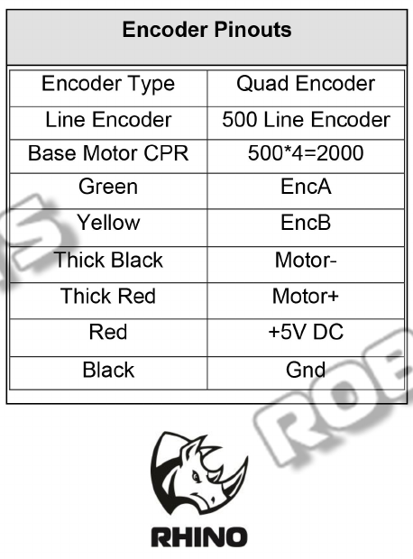
Also, they have mentioned pinouts of only four wires coming out of encoders (black,brown,red and orange) but there are total six wires coming from encoders (yellow and green coloured wires are extra).
I am not able to find use of those wires or a 6 wire output encoder anywhere.

We calculated our ppr by testing motor at 10% of its max speed (around 10 rpm) and concluded it was a 90,500 ppr encoder

I am using interrupts for all four of them to read data and simultaneously using loop function to get data from an IMU via I2C communication.

Problem comes whenever I rotate my encoders at rated speed.
Due to its very high ppr, loop function is not being able to execute as my code is going in one of four the ISR vectors continuously.

Also, output pulses of encoders are missed whenever an ISR vector is fired and hence all of my encoders are giving random data.

How can I get their data as well as run my loop function for my IMU data??

Is there a way to change frequency by which an arduino mega reads data from digital pins and send them??

In my code, I have used pin change interrupt pins using PcInt::attachInterrupt() function as my simple external interrupt pins are occupied for communication (four interrupt pins of mega are also SCL,SDA,Tx,Rx pins which leaves only 2 pins left for interrupt)

encoder_interrupt.ino (2.78 KB)
The docs are not really clear to me. If the motor is rated for 100 rpm and has a 500 lines optical encoder, this will give 833 pulses per second - no problem for an Arduino. But if the rpm is given out of the gearbox, with a corresponding motor speed of 18100 rpm, you'll get about 150kHz pulses, what's too much for a 16MHz Arduino.

first off WELCOME to the forum !!!! Glad you are here.

you have two things going on.

you have a DC motor that spins as say 2,400 RPM
you have an encoder that is connected to the motor
the encoder is say... 2,000 PPR
PPR of the motor, not the output shaft.

multiply the encoder value times the gear ratio.
you will get really high numbers.

the gearing is a mechanical thing. if you have 22:1 gear ratio, then 2,000 x 22 = encoder pulses per rotation of the final drive shaft.
so, while you are thinking super high numbers, the encoder is on the motor and much lower.
it will be a high value by the time the final shaft spins once, but revolutions per minute are motor RPM.

now, for that bit of your code that is causing the loss of counts......
not sure, but I have a pretty good idea that you will need to post your code if you want help with that bit.
my first guess is that you might be using delay() somewhere
my second is that you are not counting when other things are being executed
my third is that my crystal ball worked better when the climate was warming, now that we are entering a 33 year cooling cycle, it seems to be slowing down a bit.....

but, before you do, read about how to post code in How To Use This Forum.
it is #7 in that post.
you can find How to Use This Forum as a sticky post at the top of every forum. open it, click on the post, scroll down to #7 and it will show you about how to use CodeTags.

Since lots of people use encoders, your solution is as close as you would hope.

I see a 500 PPR encoder, if you count the rising AND falling edges of BOTH channels, that's 2000 pulses per motor rotation times gear ratio of 181 = 362000 pulses per output shaft rotation.
If you can do with 1/2 that resolution, you can use only 1 external interrupt for channel A and read channel B with a non interrupt pin to get direction of rotation.
https://robokits.co.in/downloads/RMCS%202016.pdf
From datasheet:

I would use the base encoder resolution of 500 counts per revolution, with counts triggered just on the rising or falling edge of one encoder output. That leads to 90500 counts per revolution of the gearbox output shaft.

According to the motor product page, at 18V the gearbox output shaft rotates at 108 RPM, no load. That corresponds to 326 motor shaft revolutions per second, or an encoder pulse period of 6 microseconds.

The Arduino should be able to keep track of shaft position at that rate, if your program is carefully optimized for speed, and certainly no problem if the motor is loaded and operating at lower voltage.

Keep in mind that if the Arduino has nothing else to do, polling an input using direct port access is faster than using an interrupt. For example, there are macros to check port pins.

while (bit_is_clear(PINB, 0)); //wait for high on PORTB, pin 0
count++; //count that pulse
while (bit_is_set(PINB,0)); //wait for it to clear again

For an ATmega328 (with count being declared long), this translates to the following surprisingly minimal machine code:

while (bit_is_clear(PINB, 0)); //wait for high on PORTB, pin 0
  a6:	18 9b       	sbis	0x03, 0	; 3
  a8:	fe cf       	rjmp	.-4      	; 0xa6 <inc_it>
count++; //count that pulse
  aa:	80 91 2e 01 	lds	r24, 0x012E
  ae:	90 91 2f 01 	lds	r25, 0x012F
  b2:	a0 91 30 01 	lds	r26, 0x0130
  b6:	b0 91 31 01 	lds	r27, 0x0131
  ba:	01 96       	adiw	r24, 0x01	; 1
  bc:	a1 1d       	adc	r26, r1
  be:	b1 1d       	adc	r27, r1
  c0:	80 93 2e 01 	sts	0x012E, r24
  c4:	90 93 2f 01 	sts	0x012F, r25
  c8:	a0 93 30 01 	sts	0x0130, r26
  cc:	b0 93 31 01 	sts	0x0131, r27
while (bit_is_set(PINB,0)); //wait for it to clear again
  d0:	18 99       	sbic	0x03, 0	; 3
  d2:	fe cf       	rjmp	.-4      	; 0xd0 <inc_it+0x2a>

With 4 such encoders and further I2C communication the limits of a 16MHz Arduino are exceeded, even with encoder interrupts. See the original post for the actual requirements.