Hello everyone- long-time visitor, first time poster here.
Firstly, thank you to all members of this forum for their attentive replies to those who have posted before me. I have only made it this far due to your kindness. I am having some final issues with my first Arduino project, and was hoping somebody could suggest some workarounds.
Sorry if my descriptions are poor- I am new to electronics and still have a lot to learn!
Description of circuits:
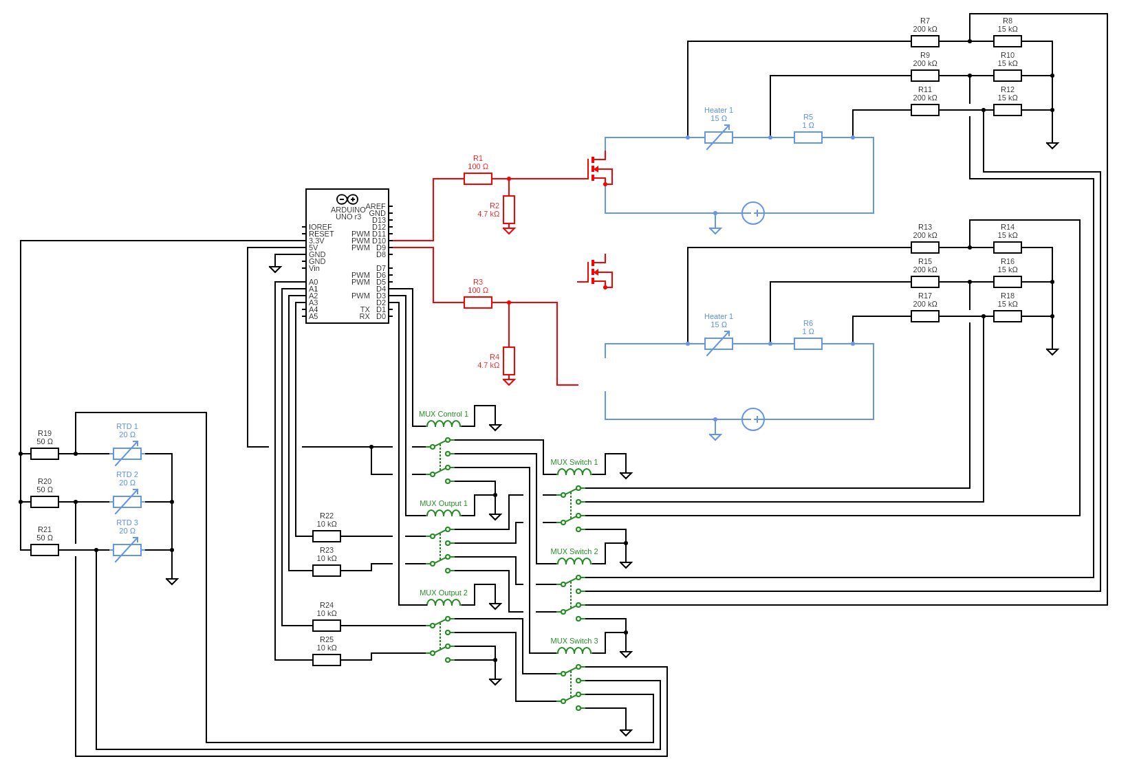
I have fabricated a microfluidic device with two platinum film heaters and three platinum RTD sensors (blue components in the attached schematic). The Arduino has four main functions:
1- Independent control of power to heaters:
The Arduino drives two MOSFETs using PWM pins, which allows an external (65 V) power supply to be throttled for each of the two heaters. This is the red part of the attached schematic, and works fine.
2- Measurement of heater power:
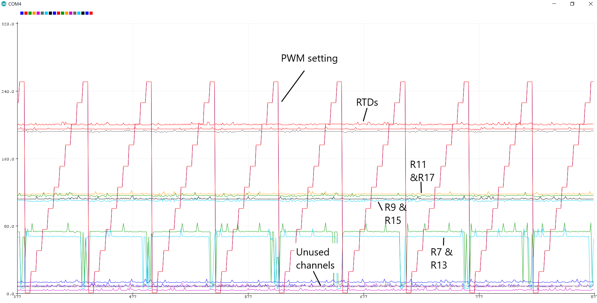
By measuring the voltage drop across the heater and across a shunt resistor, the resistance of the heater can be inferred. This is needed for calculation of heater power using V2/R. Since the power is supplied in pulsing format, the amplitude of the square wave can be multiplied by duty cycle to get the effective voltage across each component. The only way I could think to get the square wave amplitude was by taking a burst of measurements on each pin and using the maximum of these values as the square wave's top. As the measured voltage will have a 65V max, a voltage divider (200k:15k) is used at each point to give signals in the range 0-4.9 V.
3- Measurement of RTD resistance:
The RTDs (resistance ranging from 10-20 ohms) were placed in series with 50-ohm resistors, and supplied with a 3.3V reference voltage. Measuring the voltage division here allows the resistance of the RTDs to be calculated.
4- Multiplexing of these signals:
I have 9 signals and will possibly increase the number of heaters and sensors in future devices, so the signals are multiplexed using a series of DPDT relay switches (green in the attached schematic). The schematic software I used did not have these relays, so they are represented by inductors and switches.
Using a control relay (MUX Control 1), the lower-tier relays (MUX Switch 1/2/3) are switched twice as frequently as the higher-tier relays (MUX Output 1/2). Readings are taken every time the low-tier relays are switched.
All voltages are measured using the internal (1.1V) bandgap, so should be very accurate. All connections are to a common ground.
Sketch:
// --------- CONSTANTS -----------------

// Heater parameters
const int nHeaters = 2;
const int gatePins[] = {9, 10}; // control pins for MOSFET gates
const long stepUpPeriods[] = {180000, 180000}; // time between voltage steps
const float stepUpFraction[] = {0.1, 0.1}; // fraction of overall voltage per step

// Relay parameters
const byte relayPins[] = {2, 3, 4}; // Relay control pins
const byte relayIn[] = {0, 1, 2, 5}; // Analog signals
const float readingPeriod = 1000.0; // Time between consecutive readings
const int internalSkipCount[] = {2, 2, 1}; // Change of relay happens after this number of internal periods.
const byte relayCount = 3;
byte relayTrigger[relayCount]; // Used to detect when all relays have been read and start printing on a new line.
float internalPeriod = readingPeriod / 4; // Used to determine how frequently the relays are updated.

// V measurement parameters
const int numMeasurements = 20; // Number of measurements in a burst
const int burstTime = 2; // ms between measurements in a burst

// ----------- VARIABLES --------------

// Heater variables
int PWMfreq[] = {1, 1}; // PWM frequency (will run up to 255)

// Relay variables
byte relayState[relayCount];
byte trigger = 0; // Turns to 1 when internal timer is triggered


// V measurements variables
float instReading = 0; // number of instantaneous readings
byte newInstReading = 0; // slightly delayed reading for comparison
float Vref = 5.0; // reference voltage of Arduino. Will modify using internal band gap for greater accuracy
int readIndex = 0;

// Timer variables
unsigned long currentMillis = 0; // stores curernt time in each loop iteration
unsigned long previousPWMMillis[] = {0, 0}; // stores time of last power step up
unsigned long previousRelayMillis = 0; // stores time of last relay trigger
unsigned long previousReadingMillis = 0; // stores time of last reading
// ==========================================

void setup() {
  Serial.begin(9600);

  // set all heaters to their initial power.
  for (byte n = 0; n < nHeaters; n++) {
    pinMode(gatePins[n], OUTPUT); // set PWM outputs to beginning
    analogWrite(gatePins[n], PWMfreq[n]); // set all PWM rates to beginning
  }

  // set relays to their initial positions.
  for (byte n = 0; n < relayCount; n++) {
    pinMode(relayPins[n], OUTPUT); // set relay digital pins as output
    digitalWrite(relayPins[n], LOW); // set relay digital pins to low
    relayState[n] = LOW; // set relay state counter to low
    relayTrigger[n] = 0;
  }

  // designate analog inputs
  for (byte n = 0; n < (sizeof(relayIn)); n++) {
    pinMode(relayIn[n], INPUT);
  }

}

// ==========================================

void loop() {
  currentMillis = millis(); // capture current time

  // call each function sequentially
  updatePWMRate();
  relayChange();
}
// ========================================

void updatePWMRate() {
  for (byte n = 0; n < nHeaters; n++) { // runs through each of the heaters
    if (currentMillis - previousPWMMillis[n] >= stepUpPeriods[n]) { // time's up for this heater. Take action
      previousPWMMillis[n] += stepUpPeriods[n]; // update time of change
      PWMfreq[n] += (255 * stepUpFraction[n]); // update PWM frequency for this heater
      analogWrite(gatePins[n], PWMfreq[n]);

      if (PWMfreq[n] >= 255) {    // resets to beginning if we try to exceed the maximum duty cycle.
        PWMfreq[n] = 1;
      }
    }
  }
}

// ========================================

// Code to determine VCC:
long readVcc() {
  // Read 1.1V reference against AVcc
  // set the reference to Vcc and the measurement to the internal 1.1V reference
#if defined(__AVR_ATmega32U4__) || defined(__AVR_ATmega1280__) || defined(__AVR_ATmega2560__)
  ADMUX = _BV(REFS0) | _BV(MUX4) | _BV(MUX3) | _BV(MUX2) | _BV(MUX1);
#elif defined (__AVR_ATtiny24__) || defined(__AVR_ATtiny44__) || defined(__AVR_ATtiny84__)
  ADMUX = _BV(MUX5) | _BV(MUX0) ;
#else
  ADMUX = _BV(REFS0) | _BV(MUX3) | _BV(MUX2) | _BV(MUX1);
#endif

  delay(2); // Wait for Vref to settle
  ADCSRA |= _BV(ADSC); // Start conversion
  while (bit_is_set(ADCSRA, ADSC)); // measuring

  uint8_t low  = ADCL; // must read ADCL first - it then locks ADCH
  uint8_t high = ADCH; // unlocks both

  long result = (high << 8) | low;

  result = 1125300L / result; // Calculate Vcc (in mV); 1125300 = 1.1*1023*1000
  return result; // Vcc in millivolts
}

// ======================================

void relayChange() {
  if (currentMillis - previousRelayMillis >= internalPeriod) { // time to update relay trigger
    previousRelayMillis += internalPeriod; // update time of change

    for (byte n = 0; n < relayCount; n++) { // runs through each of the relays
      relayTrigger[n]++; // adds one to the trigger
      if (relayTrigger[n] == internalSkipCount[n]) { // if trigger is at specified value for this relay, relay changes

        if (relayState[n] == LOW) { // update Relays
          relayState[n] = HIGH;
        } else
          relayState[n] = LOW;

        digitalWrite(relayPins[n], relayState[n]);
        relayTrigger[n] = 0;  // reset relay trigger now.
      }
    }
    // we want to measure voltages after each relay change
    voltageReader();
    Vref = readVcc();
    trigger++;
  }
  if (trigger == 4) {
    trigger = 0;
    Serial.print(PWMfreq[0]);
    Serial.print(",");
    Serial.print(PWMfreq[1]);
    Serial.print(",");
    Serial.print(Vref);
    Serial.println();
  }
}

// =====================================

void voltageReader() {
  delay(10);
  for (byte m = 0; m < 4; m++) { // return time-maximised values from each of the analog ports
    instReading = analogRead(m);

    while (readIndex < numMeasurements) { // cycle through the values and determine the largest
      delay(burstTime);
      newInstReading = analogRead(m);

      if (newInstReading > instReading) {
        instReading = newInstReading;
      }
      readIndex++;
    }
    readIndex = 0;
    Serial.print(instReading);
    Serial.print(",");
  }
}
Unfortunately, after attaching the code my post is too long. Please see the first reply to this post for my questions.
Thank you all.