Do you like to try my multiplexing setup of Post-3? If yes, then the following is the complete wiring and test program.
1. Wiring diagram (Fig-1) among UNO, TTL <------->RS232 Converter, 4052 multiplexer, and users' RS232 devices.
Figure-1:
2. Functional diagram of 4052 multiplxer.

Figure-2:
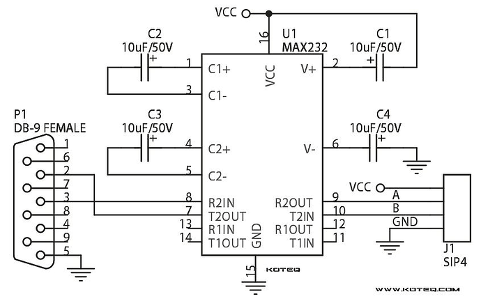
3. Schematic diagram of TTL <-----> RS232 Converter Module.
Figure-3:
4. Wiring procedures:
(1) Power down to all devices.
(2) Complete wiring connection among UNO, TTL <---> RS232 Converter, 4052 MUX as per Fig-1.
(3) With a multi-meter find "plus side (+)" of C1 (+10V). Solder one side of a jumper wire at the "plus side' of C1 and connect other side of the jumper wire with Pin-16 of 4052.
(4) With a multi-meter find "minus side ( - )" of C4 (-10V). Solder one side of a jumper wire at the "minus sid" of C4 and connect other side of the jumper wire with Pin-7 of 4052.
5. Connect RS232-0 device (Top one) to 4052 mux as per wiring of Fig-1.
6. Upload the following sketch in UNO.
#include<SoftwareSerial.h>
SoftwareSerial SUART(4, 5);  //SRX = DPin-4, STX = DPin-5

void setup()
{
  Serial.begin(9600);
  SUART.begin(9600);
  pinMode(2, OUTPUT);
  pinMode(3, OUTPUT);
  //----------------
  digitalWrite(2, LOW);  //UNO-2 is selected via multiplexer
  digitalWrite(3, LOW);
}

void loop()
{
  byte n = SUART.available();
  if (n != 0)
  {
    char x = SUART.read();
    Serial.print(x);
  }
}
7. Check that some message/data has appeared on the Serial Monitor of UNO.
8. If step-7 works, then connect other RS232 devices one-by-one. Add codes with the Sketch of UNO to select the mux channesl to select the RS232-1, RS232-2, and RS232-3 devices.

