Hello looking for a little guidance. I'm using a UNO R3 , currently reading 2 ir sensor modules HW-201 to speed up and slow down a small dc motor. Im using a hardware interrupt on the first sensor to change the speed till the second sensor is triggered. then slow down . Ive stripped the code down to just the speed up routine but the second sensor doest always trigger . the module triggers but the code doesnt see it .
the code works ok if the speed is slow enough .
Thank you for your time
#include <SPI.h>

const int IRpin = 2;
const int IR1pin = 3;
const int motorpin = 9;

volatile int IRsensor0;
volatile int IRsensor1;
int speed = 42;

/*************ISR function*******************************/
void speedup(){
   // while(IRsensor1 != HIGH)
      do {
         //speed = map(buffer.toInt(), 0,1023,0,255);

        analogWrite(motorpin,speed+25);
        IRsensor1 = digitalRead(IR1pin);
       }while(IRsensor1 == HIGH);
 //            IRsensor1 = analogRead(IR1pin);

       analogWrite(motorpin,0);
   //    delay(10);

}

/***************************************************/

 void setup() {
  pinMode(IRpin, INPUT_PULLUP);
  pinMode(IR1pin, INPUT_PULLUP);

  // Open serial communications and wait for port to open:
  Serial.begin(9600);
  while (!Serial) {
    ; // wait for serial port to connect. Needed for native USB port only
  }


  attachInterrupt(digitalPinToInterrupt(IRpin),     speedup, CHANGE);


 }

 void loop() {

analogWrite(motorpin,speed);

/*      IRsensor0 = digitalRead(IRpin);
      IRsensor1 = digitalRead(IR1pin);

Serial.print(speed);
Serial.print("  IR0 ->");
Serial.print(IRsensor0);
Serial.print("  IR1 ->");
Serial.println(IRsensor1);


  delay(250);*/
 }
Hello, and thank you for your advice . I made the changes like you suggested . I now have two interrupts speedup and slowdown . I did use two write statements in the slowdown ISR, is that an ok thing to do? seems to work pretty well ,the problem with the second sensor not triggering the arduino turned out to be interference from the electric motor. I re-routed the sensor wire and that problem virtually went away.
Here's a copy of the new code.
Thank You
#include <SPI.h>
//#include <digitalWriteFast.h>
const int IRpin = 2;
const int IR1pin = 3;
const int motorpin = 9;

volatile int IRsensor0;
volatile int IRsensor1;
int speed = 42;

/*************ISR function*******************************/
void speedup(){
        analogWrite(motorpin,speed+45);
}

/*************ISR2**************************************/
void slowdown(){
        analogWrite(motorpin,0);
       // analogWrite(motorpin,0);
        analogWrite(motorpin,speed);
}
/************************************************/

 void setup() {
  pinMode(IRpin, INPUT_PULLUP);
  pinMode(IR1pin, INPUT_PULLUP);

  // Open serial communications and wait for port to open:
  Serial.begin(9600);
  while (!Serial) {
    ; // wait for serial port to connect. Needed for native USB port only
  //  analogWrite(motorpin,speed);

  }

  attachInterrupt(digitalPinToInterrupt(IRpin),     speedup, LOW);
  attachInterrupt(digitalPinToInterrupt(IR1pin),     slowdown, LOW);

analogWrite(motorpin,speed);
 }

 void loop() {
   // analogWrite(motorpin,speed);

/*Serial.println(speed);
Serial.println(" ");*/
/*      IRsensor0 = digitalRead(IRpin);
      IRsensor1 = digitalRead(IR1pin);

Serial.print(speed);
Serial.print("  IR0 ->");
Serial.print(IRsensor0);
Serial.print("  IR1 ->");
Serial.println(IRsensor1);

*/
  //delay(250);
 }
Hello all , so I made changes to the ISR's that were suggested. Much better now, it's about 98-99%. However I'm having a noise problem at the moment and I am anticipating a fast read problem it the next phase.
Should I close this thread (since effectively the original question was answered), and start another describing the project in full and the noise problem?
Updated code.
#include <SPI.h>
//#include <digitalWriteFast.h>
const int IRpin = 2;
const int IR1pin = 3;
const int motorpin = 9;
volatile int speedupFlag;
volatile int slowdownFlag;
volatile int IRsensor0;
volatile int IRsensor1;
int speed = 70;
//int i=0;

/*************ISR function*******************************/
void speedup(){
        speedupFlag=HIGH;
}

/***************************************************/
void slowdown(){
       slowdownFlag=HIGH;
}
/************************************************/

 void setup() {
    pinMode(IRpin, INPUT_PULLUP);
    pinMode(IR1pin, INPUT_PULLUP);

    // Open serial communications and wait for port to open:
    Serial.begin(9600);
    while (!Serial) {
      ; // wait for serial port to connect. Needed for native USB port only

    }

    attachInterrupt(digitalPinToInterrupt(IRpin),     speedup, LOW);
    attachInterrupt(digitalPinToInterrupt(IR1pin),     slowdown, LOW);

    analogWrite(motorpin,speed);
 }

 void loop() {

      if(speedupFlag != LOW){
        speedupFlag= LOW;
        analogWrite(motorpin,speed+70);
      }

      if(slowdownFlag != LOW){

                slowdownFlag=LOW;
                analogWrite(motorpin,0);
                delay(70);
analogWrite(motorpin,speed);

      }

}
Thank you , im new to this forum thing.
Agreed, i thought i had the noise problem addressed. It appeared to be a problem with speed the sensor was being triggered. With your alls help, the code is much more efficient and working like it should .
So the noise is being generated by the small electric motor 1/64 scale slot car to be exact. That we're controlling from the hacked MOSFET circuit of a dc to dc PWM controller via pin7. The reason i thought i had the noise problem addressed , i used a car that had noise suppression.
Here are a couple pics of the project . The ir sensors are powered from the arduino. The dc to dc coveter gets is power from a standard hobby transfomer 22vdc 7va . The pwm controller is grounded to the arduino. Ill shoot you a pic of the whole thing shortly.
This is the test rig . The ir sensors are powered with 5v not 3.3 like in the one pic . The wire for the IR sensors is shielded . It goes around to the end of the table to a breadboard then to the arduino. Everything is grounded to the same plain .
So I changed the proximity of the Arduino, breadboard and controller. moved it off the table to chair beside . That seems to have made a huge difference. It ran error free . long enough to detect another potential problem . The car started to slow . It was getting hot. the car is not happy with this short track and the frequency of the PWM. I have used this PWM before but its on the front end of the circuit. Meaning wall transformer to PWM (has a 10k pot to adjust the % out) , to track to regular transistor type controller to track . wiring diagram attached.
The way its currently hooked up is. wall pack to PWM directly to track rails . ordinally you would use the 10k pot to adjust the speed but it cut the trace just before the MOSFETS and jumper over to the Arduino pin 7 digital out .
I also I tried a digital pot to control the PWM but it won't respond quick enough.
Now having said all of that and made what I consider progress or at least I've learned a bunch. I am not married to this PWM controller. I am not opposed to going a different direction. I just happen to have five of them laying around. I used them on the main track to adjust max voltage for inexperienced users. I've since gone a different direction . One of the PWM controllers was bad so I dissected it hoping I could use parts to build what needed. took the numbers off the MOSFETS looked them up got the pinouts and noticed the trace on control pin . so I was able to use that trace on the board and leave everything intact. and this is how I got here. Voltage out on the PWM hooks to Red and Black.
Hopefully this makes sense.
Thanks for taking the time help me
That diagram you posted is very confusing because for some reason it shows the negative line in red and the negative line in grey and black.
What exactly are the driver stations? I am assuming that these are the "wall pack to PWM" you talked about. What are the numbers identifying the FET? It could be that they are not suitable for how they are being driven, and the car is getting hot for this reason.
Understand that if you supply a PWM signal to all of the tracks, this in its self will generate a huge amount of RFI (Radio Frequency Interference). What frequency of PWM are you generating?
Thanks Mike for your help . Sorry if I made everything more confusing. You are quite right about the wire color . I never have figured out why they colored the wires the way the do .
The Driver stations are where the normal controllers hookup. one for each lane.
both of these controllers are higher end .
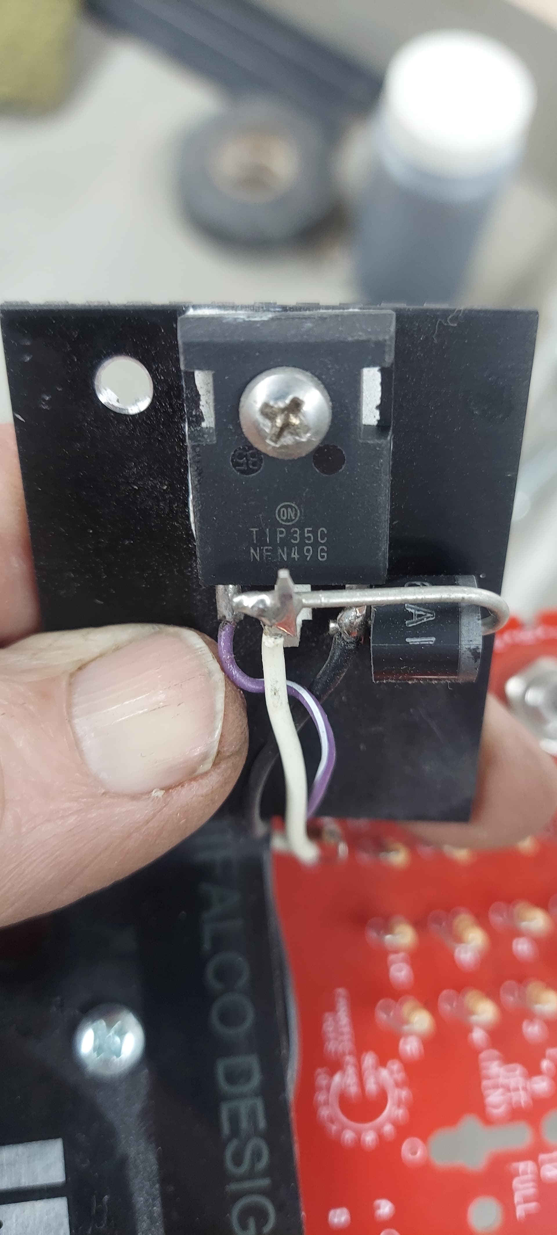
The Green controller is a 2 wire hookup (no brake) restive array with a BJT and a 6A1 diode.
The Clear one is higher end 3 wire hookup(brakes) I think this one is PWM I could be wrong . Their are some that do .
The slot car corner diagram, is a standard across the board in the slot car world.
ordinarily you would hookup a controller at the driver stations . Terminals Red black and white. The controllers, on the low end are nothing more than an adjustable resistor . they hookup with two wires (black & white terminals on the drawing ).
Now to make it more confusing some of the higher end controllers use a 2 or 3 wire hookup depending on if it has brakes. (red,black and white). they use arrays of resistors a wiper and a BJT tip35c.
We also have even higher end controllers that are PWM with the 3 wire hookup
I'm not smart enough yet, to even try to explain what's going on there.
Also in the diagram there is no PWM its just a hobby wall pack 22vdc 7va or adjustable power supply to the track .
Ok so that is the standard .
Now broad terms
My goal is to use a micro controller to control the speed of a slot car. using IR sensors or possibly Hall sensors located at entry and exit of straight away to speedup and slowdown.
The FET K3599 I pulled one out of a broken PWM controller put it on a breadboard to figure out how to use it with the Arduino . Then i noticed the trace on the board for the control pin . On a good PWM controller I cut the trace and wired the control pin to the Arduino and Wala I could control it . As for the FET's not being suitable to be driven that way , that is entirely possible. I have no idea. This is what I mean when I say uneducated . I have had zero formal electronics education .
One last thing in the pics with the PWM controller. I have the (PWM out) hooked directly to the rails via driver station red and black.
I hope this helps.
Thank you again
The relevant parameter is called Drain source on resistance (Rdson). This is the voltage on the gate you have to get for the FET to turn on as hard as it can. Anything lower is in the what is called the linear mode, where it dissipates a lot of heat. So this would get "mad jumping hot" as my school metal work teacher used to say.
Me too. In my day nobody knew the term Electronics. I had to say it is like the inside of a transistor radio, but it is not a radio.
Also the wiring of the TIP35C looks wrong. This must have a resistor in series with the base, and I can't see one. So this could get very hot as well.
Honestly I didn't check the controller. Just the car . So I was looking at the circuit on the pwm board. The out bound side ground plain is isolated from the rest of the board. Not sure if that means anything. Here's a couple pics top and bottom.
So what if I scraped this whole pwm controller . And build one. The current draw is typically 2-3amps max voltage rarely above 25dc . I've got a couple of assortments of FETS
On TIP35C . It has boat load of resistors on the board . I'm sure it has one the resistor you speak of . The heatsink will get warm/hot depending on the car . Especially if it's a big magnet car. The TIP35C pics are the inside of the green controller. Laying on the track
Something you said about the K3599 FET got me thinking. when I probe the trace I drive it from on a working PWM running at full tilt I read 5v well very close.