Hi All,
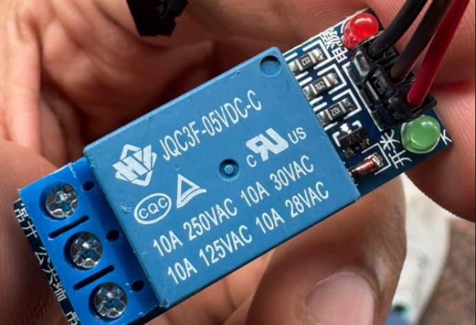
I m implementing a home appliance automation using ESP8266 interfaced with Relay Module JQC3F-05VDC (as a switch). The two LEDs on relay module is working fine but the relay is not mechanically changing its connection internally.
as a big Picture, here is the connection details:
ESP8266 :
Power source is 5V DC via USB
D2 is the set as output for controlling the relay Module INPUT
So for two cases I have tested it out - 1) Applying 3V from ESP82666 to Vcc of relay and GND to GND
From this the LED green is correctly working whenever the INPUT D2 terminal changes , but with that the CLICK sounds comes rarely. Many a times i need to tickle the Relay by any object (say any pencil) to get the click sound. This NOT clicking of relay is affecting my output terminals and Hence the system is not working with accuracy.
Other Observations - Voltage across Relay = 3.26V
2) Applying external power source of 5V to relay (Vcc and GND)
With this there is no reaction on green LED. It stays off only independent of the INPUT signal.
I am not sure how to deal with this issue, I have seen throughout the internet but never saw this sort issue and its resolution listed anywhere.
Take a photo of a hand drawn wiring diagram. Your photos are ambiguous.
Also post all your code in code tags.
Be aware some relays are solid state and do not click. Hook up a load (a flashlight battery and bulb will do or a VMM set to continuity or ohms)
It is quite common for breadboards to have bad internal connections and are easily overloaded thus damaging and corroding the terminals. Use one of those green screw connectors like your relay board uses. Also wiggle any dupont wires, cheap wires sometimes have bad pin connections. I tossed hundreds of them in favour of silicone wires, MUCH better.
Hi, for case (1) the relay needs 5v to work reliably so what you are seeing with circa 3.3v is not unexpected. For case (2), did you connect the GND from your external source to the GND of your board?
As stated, your relay's required coil voltage is 5 volts. You are trying to activate it with 3.3 volts. You either need a relay with a 3.3 volt coil or a switch wired to 5 volts to switch on the relay.
This was enough to understand the problem. The ESP8266 is a 3.3V device, the relay module is a 5V device.
I know you are providing 5V power to the module, but the signal is only 3.3V. The module was designed for 5V signal.
The 3.3V signal is enough to light the LEDs but not enough to trigger the relay itself.
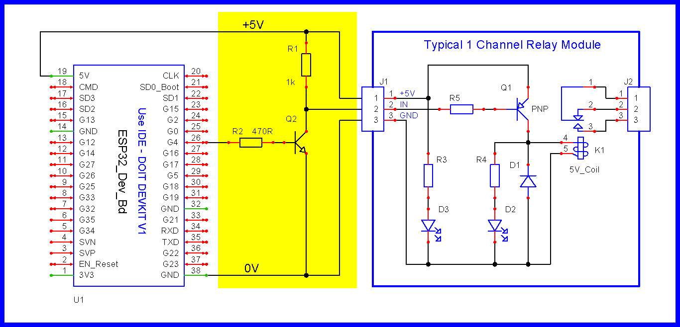
You need to use a transistor of some kind to increase the 3.3V signal to 5V.
Next time, choose a relay module that is compatible with 3.3V signals. Good luck with that because the manufacturers don't give that information. It might hurt their sales. No, I can't recommend a module for you. I would need to do research, which is what you should do.
But what will be switched by the relay module? Maybe something better than a relay could be used?
HI PaulRB, i even tried giving 5V to relay module in Vcc and gave the 5v signal too but it becomes subtle with only red light ON. I can again try with this case.
I need to search if there is any relay that operates on 3.3v.
This relay would be handling AC current by acting as a swtich for an external appliance connected at NC and C of relay Module.
Do we have any better option apart from relay that can act as a switch to control AC current?
@sayjdeez I have been experiencing the same issue for several months now. In my case, the problem lies with the quality of the blue relays; they simply do not withstand mechanical stress. A slight mechanical impact or a complete system reset can temporarily restore their function, but they tend to become stuck again after a short while. This serves as a reminder that with lower-cost components, you often get what you pay for.
Adding load to the main contacts should, in theory, not affect the operation of the control coil. Remember: even though these relays are rated for 10A, I am uncertain whether they would reliably handle even 5A over time. In my particular application, I plan to use the relay to control the coil of a more professional-grade relay, such as those from Phoenix Contact, Siemens, or Omron. I am considering switching to a Solid-State Relay (SSR) instead of relying on these blue relays.
Use a ESP development board with a 12V supply. This arrangement provides all the necessary voltages and power required for the system, with the exception of the USB from the ESP, which cannot supply much power. Additionally, while using an external 5V supply may not resolve the issue, it is important to ensure that the ground (GND) is common across the system. An ESP development board should be sufficient to handle these requirements.
I agree with PaulRB’s point regarding the use of an SSR. However, one consideration with SSRs is that, when the control signal is at 0V (inactive), there is still a small current flowing through the relay. Although this current is minimal, it may still have an impact depending on the specific requirements of your application.
Can you please post a copy of your circuit, a picture of a hand drawn circuit in jpg, png? Hand drawn and photographed is perfectly acceptable. Please include ALL hardware, power supplies, component names and pin labels.