This is a charger. There is no motor. It only charges a 48v battery pack. The battery pack is in a golf cart. No need for that.
After looking around, I am pretty sure that the 48vdc from the battery pack is what powers up the PCB. Once powered up by the 48vdc from the pack, it then “senses” whether or not the charger should turn on the transformer and produce dc voltage through the PCB. There are two sealed potentiometers on the PCB that I assume adjust the voltage and amps at which the charger turns on and off and maybe how many amps it produces for a trickle charge when the battery pack is close to charged? Here is a better pic of the PCB.
There are only 3 components really. The relay (which I think is indeed a safety of some kind though I don’t know how it works), the transformer, and one single PCB which is pictures below:
Look at the diagram on page 3 of the datasheet and tell us which wires go to which terminals on the relay. The coil terminals are at the top, the contact terminals are below the coil terminals and labeled NC, NO and COM. https://www.alliedelec.com/m/d/be6f954ea2011718d470cc0e43a43aa2.pdf
I’m not sure what I am missing here. The charger is an external charger. Separate from the golf cart. It would charge any 48v battery lead acid battery pack. It wouldn’t have to be in a golf cart. It could be used to supplement a solar array. The golf cart really has nothing to do with it. The charger itself
Is what is not working properly.
The second sentence of the very first post in the thread clearly says golf cart CHARGER…. It does charge a golf cart but the golf cart is irrelevant to the problem which I have been trying to explain the best I could.
Lets try something basic - is the charger marked with any brand name or model number? The entire schematic or service manual may be available online somewhere, or at least maybe the owner manual.
< edit >
Looking at the PC board, it is labeled "Diversified Power International". A search for that shows that some of their chargers use a relay to disconnect the AC power from the transformer when the battery is fully changed, to save power. The relay is controlled by the PC board, and would need a battery connected in order to power the circuitry that controls the relay. This MAY NOT BE the function of the relay in the charger you have, only speculation based on other chargers made by the manufacturer.
Nothing. No led lights, no relay clicks, nothing. I thought before that when the main power was plugged in that the led lights would illuminated and indicate that there was mains ac power to the PCB , but now I am doubting my memory.
I am wondering if the PCB is only powered up and can begin charging if the 48v is connected(no lights illuminate until the charger detects battery pack voltage) . The golf cart itself has a volt meter mounted on it which read 48-49v. and when I was trying it. However, I am not at the cart at the moment, but I am wondering if I have a problem at the receptacle of the golf cart or in the chord to the charger that is not allowing the voltage to get to the charger PCB. This would prevent the PCB from coming on.
I just thought I remembered the led lights coming on whether it was charging or not if the main power was connected. Maybe not?
This sounds exactly like it could be what I have! Obviously I’m not a electronics guy. I looked at the diversified powered PCBs, but i wasn’t sure how they functioned. Although I am interested. It appears fairly simple, yet I don’t understand it.
How would it work?
Battery pack voltage comes in and powers the PCB/microcontroller, if battery pack voltage is below some preset voltage, the charger turns on (somehow maybe the relay in question?), if their is main ac power from the wall, the transformer reduces the 120v from the wall to some lower manageable voltage (60vac?). That ac voltage goes in to the PCB to be “rectified” with some diodes (which id love to understand). now the dc current can be sent out to the battery pack to charge the batteries. Once the battery pack reaches some set voltage that is “charged”, the ac power must be disconnected to prevent overcharging the batteries. This is where the relay comes in? I don’t understand how because I thought that relay was “activated” with 120vac.
I’d love for someone to explain how the process may work. I know there are probably a million ways to do it, but it seems like with no more components that are on this PCB it can’t be too difficult. I do appreciate all the help!
Thanks everyone!
@Paul_KD7HB i didn’t mean to be misleading, I was trying to provide all the info the best I could. Sorry.
That is usually how the big ones work, they must see battery volts before switching the mains.
Some have a "Dead Battery" button to try and put a low charge rate in initially to get the voltage back up if the battery is viable.
The control circuit runs on current from the battery.
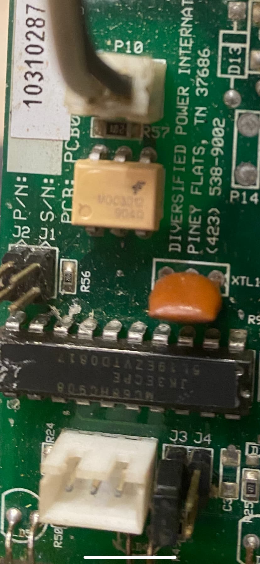
The relay has a 120V coil. One side looks to be connected to the hot wire (black) at the relay itself, the other side likely goes to the two-pin connector labeled P10 on the circuit board. Near this connector is a six-pin DIP packaged chip, can't quite make out the numbers, but could be an opto-coupler used to switch the relay coil.
The relay wiring is shown in some of the manuals, but can't find any schematics for the circuit board using google.
The large chip with the sticker labeled DP4814A8/A01R60 is likely a microprocessor, googling the number shows some reference to that as a software version number. The manufacturer's website has a very similar picture on their replacement board page, but no actual listing for the 48 volt version. https://www.dpipower.com/replacement-parts/controller-boards.html?product_list_limit=all
This is what is under the sticker. This I am assuming is the actual chip. I figure that the company loads there “code” on to this chip and the identifying number you are talking about is to identify what version of code is uploaded? Maybe for differing voltage chargers? I am completely guessing here.
So, the micro processor is getting information from some PCB component as to how many volts the battery pack has. If it needs to turn the charger off because the pack is at full charge, it sends a signal to the optocoupler, which then sends voltage to that relay? This cuts the main ac power off to the transformer?
Again, I’m completely guessing, but would love to know.
Thanks!
Edit: here is what is on the chip you are referring to and in the picture in this post:
MC68HC908 is a microcontroller, basically works the same way as the processor in an arduino. No telling exactly how the rest of the boards works.
If it is non-operational, the first thing would be to make sure you are getting a good connection to the battery, and that the board was getting power to the electronics. The processor Vcc is a maximum of 6V, so there would need to be a voltage regulator somewhere on the board. Be careful if you decide to start measuring things, DO NOT plug the charger into 120V, that should not be necessary since the electronics appear to be run off the battery. 48V is getting high enough to be a shock hazard, and accidentally shorting the battery will destroy things (a 12V car battery easily supplies enough current to weld metal parts together).
Out of curiosity, if the PCB is bad, which I am thinking it isn’t now, what would the process look like to repair it? I’m assuming if the microprocessor is bad, there would be no repair without an exact replica that has the proper code loaded?
If the microprocessor is good, would it be difficult to trace down which component was bad and replace it?
You are correct about a bad microprocessor, it would need to be replaced with a processor with the proper code on it.
As to how difficult it would be to repair the remainder of the board, that would depend on how experienced you were with electronic repair - and from the questions you have asked, it does not sound like that is your main line of work. Working without a schematic makes things very difficult.
I would start by just checking that all the connectors were making good contact, those can corrode over time, so pulling the connector off and putting it back on will sometimes get things working.