Hi there,
Can someone up here, give me an advice for replacing a normal resistor with a SMD-Resistor ?
I need SMD Resistor for these types:
270 Ohms
I need a special item on aliexpress
I wanna use these SMD-Resistors as a PULLUP for a PUSH-BUTTON.
You might use the Arduino internal pullup resistor.
yes, I will check this. Maybe this is a good solution
270 or 100 ohms would be very small values for pullups
2 Likes
yes, this ones, I wanted to use as a voltage devider, from 3.3V to 0,9V. Wanna use it for an AnalogRead. But the 10K ones, for an PullUp. But, as @paulpaulson said, I should use the internal pullups
Post the current schematic.
I have no shematic yet. I just tested it out on a breadboard.
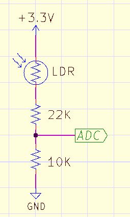
it is like this. The AnalogRead from the ESP8266 accepts only a maximum Voltage of 1V. Therefore, I hade to devide the voltage
Please forget my first shematic, look again here...
6v6gt
August 12, 2023, 10:46am
11
Look at the Analog pin of the Wemos D1 ESP8266 module: https://user-images.githubusercontent.com/53401742/71557972-7db54b80-2a13-11ea-9179-e96319fe7f2b.jpg for example values of the voltage divider.
You may also notice that this scheme means that the voltage divider goes after the connected device (LDR in your case) .
LarryD
August 12, 2023, 2:43pm
13
If you redraw this you will see GPIO15 is shorted to GND.
GPIO02 is connected to 3v3
270R/100R voltage divider gives .9v to the LDR/10k voltage divider.
.9v / 100R = 9mA thru the 100R resistor.
BTW, you should draw schematics in a more standard way.
I see no push button. Is there a coil spring in there? 'cos I wonder if you are winding us up.
SMD resistors come in several different physical sizes. Which size do you need?
1 Like
sorry, was working (yes, on sunday).
It should be hand solderable. I think it was 1206 imperial size
And do the original pads have plated through holes or did they rely on the resistor leads for electrical connection to the back side of the board?
1 Like
the PCB will be drawn by me, so therefore, i will make some good pads for the 1206 imp size.
westfw
August 13, 2023, 10:34pm
19
Anything should work fine. While your voltage divider resistors are of unusually low values, their power dissipation is still quite low (3.3V/370ohm = ~9ma. 9mA through a 270ohm resistor is 0.02W, so even those itty-bitty 1/16W 0402 resistors would be OK.
Note that 1206 resistor PCB footprints are somewhat disappointingly large - bigger than a vertical mount TH resistor
1 Like
Yes, I guess this would be a problem. It is going to be a two-layer-pcb.


