Require guidance in my new project

The example sketch I used for the ultrasonic sensor.

#define trigPin 19                    // A5
#define echoPin 16                    // A2
#define redLED  14                    // A0

long duration, cm, inches;

void setup() {
  Serial.begin(9600);
  pinMode(redLED, OUTPUT);
  pinMode(trigPin, OUTPUT);
  pinMode(echoPin, INPUT);

}

void loop() {

  digitalWrite(trigPin, LOW);
  delayMicroseconds(5);
  digitalWrite(trigPin, HIGH);
  delayMicroseconds(10);
  digitalWrite(trigPin, LOW);
 
  pinMode(echoPin, INPUT);
  duration = pulseIn(echoPin, HIGH);
 
  cm = (duration/2) / 29.1;            // Divide by 29.1 or multiply by 0.0343
  inches = (duration/2) / 74;          // Divide by 74 or multiply by 0.0135
  
  Serial.print(inches);
  Serial.print(" in, ");
  Serial.print(cm);
  Serial.print(" cm");
  Serial.println();

  if (cm <= 10) {
    digitalWrite(redLED, HIGH);
  }
  else {
    digitalWrite(redLED, LOW);
  }
  delay(100);
}

Why the pinMode for echoPin in loop()?

digitalWrite(trigPin, LOW);
  delayMicroseconds(5);

Why? trigPin should already be LOW.

TheMemberFormerlyKnownAsAWOL:
Why the pinMode for echoPin in loop()?

digitalWrite(trigPin, LOW);

delayMicroseconds(5);


Why? trigPin should already be LOW.

I really don't know. It is the first time I am dealing with an ultrasonic sensor. It is an example sketch copied from the website, which I used.

I seem to remember that some types of these sensors have a combined trigger and echo pin, so it would be necessary to change the pin mode in loop(). The fragment may be from code designed to be configured for sensors with combined or separate trigger & echo pins.

I saw some other example sketches and I came to know that there is no need to have pinMode for echoPin in loop. However, almost all of them have made trigPin low then high and then low as in the sketch. Hence that is correct, I presume. I removed the pinMode for echo from the loop in my sketch and it is working as expected.

bilal40:
However, almost all of them have made trigPin low then high and then low as in the sketch. Hence that is correct, I presume.

"correct" if you're practising defensive programming (something else could have written trigPin HIGH), "lazy" or "sloppy" otherwise.

Hi everyone,
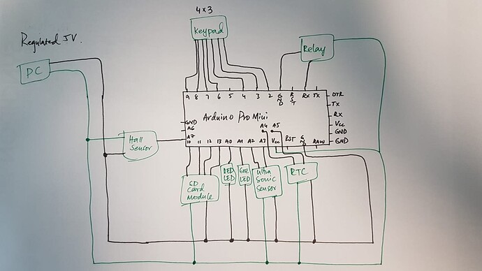
I am almost at the final step of my project and facing an issue that I need to discuss here. Attached is the schematic of my project to this message. I am using a Pro Mini 5V 16 MHz version, a 4x3 keypad, hall sensor, ultrasonic sensor, RTC, a memory card, one relay (that I am opting to replace with MOSFET), one red and one green LEDs are connected to the Arduino. As my system would be running on a battery, therefore, it was important for me to keep the current as low as possible. Therefore, after the use, I bring the Arduino to deep sleep mode. The current measurements are given below. In all the cases given below the Arduino itself is in deep sleep mode.

Peripherals Ultrasonic sensor Hall Sensor sd card module RTC Relay Current (mA)
Case 1 OFF OFF OFF OFF OFF 4 mA
Case 2 ON OFF OFF OFF OFF 7 mA
Case 3 ON ON OFF OFF OFF 13 mA
Case 4 ON ON ON OFF OFF 14 mA
Case 5 ON ON ON ON OFF 19 mA
Case 6 ON ON ON ON ON 19 mA

When the Arduino wakes up and all other peripherals are in ON state the current goes to 31 mA. The ON and OFF state of peripherals means, when the Arduino was in deep sleep mode, I disconnected the peripherals one by one and measured the current. So, if I don't turn OFF anything, the minimum possible for me is 19 mA, if I turn off everything when the Arduino is in deep sleep mode, I can achieve up to 4 mA and that would great.

So, my question is would it be possible to turn OFF every peripheral when Arduino is in deep sleep mode, and when it wakes up all the peripherals should wake up, too?

I am planning to use a MOSFET as a switch and before going to deep sleep mode, I disconnect the GND of all the devices through the MOSFET, and when wake up connects them back. Or is there another better way to do all this?

I am also planning to remove the power LED from the RTC and the Arduino and see how much would it reduce, I don't know but I think it won't be so much. I can not remove the regulator from the Arduino as I would be providing it with an unregulated voltage from the battery pack.

Any suggestions, please? Thank you

Post a real schematic please. And links to specs of all components/modules.

@Paul, I sure will do that tomorrow first thing in the morning.

One more thing which I am figuring out is the interrupt call from the keypad button to wake up the Arduino is still unresolved. Today, I saw a post on the forum The interrupt usage with keypad - Programming Questions - Arduino Forum that is exactly what I want to implement but unfortunately, I am not able to get the exact idea.

void Going_To_Sleep() {

  sleep_enable();
  attachInterrupt(0, wakeUp, LOW);
  set_sleep_mode(SLEEP_MODE_PWR_DOWN);
  delay(1000);
  sleep_cpu();
}

void wakeUp() {
  sleep_disable();
  detachInterrupt(0);
}

I call the sleep function as shown above in the code, it makes the Arduino sleep, then I connect pin 2 to the ground to wake it up. However, I want the # button to be pressed when Arduino is in a sleep state to wake it up.

What changes do I need to make in the code? Do I need hardware change as well? Currently, my pin 2 is the pin to be used for interrupt and is not connected to anything. Pin 3 to pin 9 are connected to the keypad. # button is connected to pin 9 (column) and pin 5 (row) on the keypad. May I know how to make this happen?

Thanks

You could change keypad pins so that pin 2 is connected to either the row or column for #. Let's say you connect pin 2 to the row for # and pin 9 to the column for #. Before sleep, you would set pin 2 to INPUT_PULLUP and pin 9 to OUTPUT, LOW. If # is pressed, pin 2 would change from HIGH to LOW, causing wake from sleep.

PaulRB:
Before sleep, you would set pin 2 to INPUT_PULLUP and pin 9 to OUTPUT, LOW. If # is pressed, pin 2 would change from HIGH to LOW, causing wake from sleep.

@Paul, thank you so very much. I did as you directed and it is working like a charm. Below is the change that I made to the sketch. But one question, during wake up, as I have commented it below //pinMode (9, INPUT).... should I bring it back to the input form? It is working fine even I haven't changed it back to the input but is it going to make a problem?

void Going_To_Sleep() {

  sleep_enable();
  attachInterrupt(0, wakeUp, LOW);
  set_sleep_mode(SLEEP_MODE_PWR_DOWN);
  delay(1000);
  pinMode(interruptPin, INPUT_PULLUP);                    // interruptPin is 2 on arduino
  pinMode(9, OUTPUT-LOW);                                 // changed pin 9 to OUTPUT-low here
  sleep_cpu();
}

void wakeUp() {

  sleep_disable();
  detachInterrupt(0);
  //pinMode(9, INPUT);                                       // Should I change pin 9 back to INPUT or no? 
}
pinMode(9, OUTPUT-LOW);

That doesn't do what you think it does. It works, by luck, because outputs default to LOW.
"OUTPUT" and "LOW" are pre-defined constants. I'm not sure what value OUTPUT has, but I'm pretty sure LOW has value 0, so OUTPUT-LOW (OUTPUT minus LOW) has same value as OUTPUT.
You should put

pinMode(9, OUTPUT);
digitalWrite (9, LOW);

should I bring it back to the input form?

Maybe. I don't know how you are scanning the keypad, what library you may be using. It is possible that the keypad library sets the mode of each pin when called from setup() and if you change the pin's mode later, the library might stop working. But it is also possible that the library sets the mode to INPUT_PULLUP and setting to INPUT could cause problems. Does the keypad library have a begin() method? Maybe call that again when waking from sleep.

@PaulRB, attached is the complete schematic and the components I used are given below.

  1. Ultrasonic Sensor HC-SR04
  2. Hall Sensor (https:://docs.rs-online.com/e64f/0900766b8106a158.pdf), I am using the UA package.
  3. DS3231 real-time clock
  4. 2 relay module optocoupler (On your suggestion, I would change it to a MOSFET)
  5. Keypad 4x3
  6. Micro SD card module bought it on Amazon, the link is given: (https://www.amazon.de/dp/B077MB17JB/ref=sspa_dk_detail_0?pd_rd_i=B06X1DX5WS&pd_rd_w=GPci7&pf_rd_p=907efdef-64f0-4d54-bac1-a1aa35942c8f&pd_rd_wg=3OT9I&pf_rd_r=Z22CH21TNEPMZPA97BB5&pd_rd_r=08f26063-8142-4d07-b9ce-50bfeb4c23fb&spLa=ZW5jcnlwdGVkUXVhbGlmaWVyPUFZTjM4MTFXQUNBS00mZW5jcnlwdGVkSWQ9QTA0MTcwMTYzNkRRN1ZWNlZTODJWJmVuY3J5cHRlZEFkSWQ9QTAzMzE2NTEzREIwWUNZSDI5UDhYJndpZGdldE5hbWU9c3BfZGV0YWlsX3RoZW1hdGljJmFjdGlvbj1jbGlja1JlZGlyZWN0JmRvTm90TG9nQ2xpY2s9dHJ1ZQ&th=1)

PaulRB:
Does the keypad library have a begin() method? Maybe call that again when waking from sleep.

No, there is not begin() for the keypad. I am using <Keypad.h> library. Before setup(), I am doing this:

#include <Keypad.h>

const byte ROWS = 4;
const byte COLS = 3;
char hexaKeys[ROWS][COLS] = {
  {'1', '2', '3'},
  {'4', '5', '6'},
  {'7', '8', '9'},
  {'*', '0', '#'}
};

byte rowPins[ROWS] = {3, 4, 2, 6};                                                     
byte colPins[COLS] = {7, 8, 9};

Keypad customKeypad = Keypad(makeKeymap(hexaKeys), rowPins, colPins, ROWS, COLS);

that's all for the keypad.
You highlighted one thing that if the keypad had begin() method I should call it again, so, I wanna if we have a begin() for components, do we need to call them all the time after the Arduino wakes up? For instance, the RTC I am using has an rtc.begin(), and similarly, the sd card has initialization in the setup, so right now when I put the Arduino to sleep and wakes it up, I don't call their begin and they are still working. Or we only call the begin method when the power is cut down to those components?

Looking at the standard Arduino keypad library code, it sets pin modes and output levels explicitly for each pin, each time it scans the keypad. So you don't need to do anything with pin 2 on waking. I should say that reading the code inside a library to see how it works can be a dangerous thing. Maybe one day the library code will be changed, and what I said will no longer be true, and if you then re-upload your code after that, it could stop working. So it's best to avoid reading library code and making assumptions that it will never change. But in this case, I can't see another way.

Calling a library's begin() function after waking the Arduino is not normally neccessary. But if you put the component to sleep, it might be neccessary when you wake it. There is no simple yes/no answer. You have to learn about each component and it's library to figure out what must be done, if anything, when you wake it.

For the hall sensor, you cannot put the component into a sleep mode. The only thing to do is power it down. It requires only 14mA maximum, so you can power it from an arduino pin. That means you will need an analog input pin and a digital output pin for the sensor. You can power down the sensor by writing LOW to the digital output pin and power it up by writing HIGH. After powering up, you should have a short delay, 32us, before you read the analog pin. You may need to discard the first analog reading and take a second reading.

Understood. By now it is working fine but I face one issue. Generally, the program works like if you give the correct password of 7 digits, it will open the lock, and then the Arduino goes to sleep mode. Now, if I press the # button, it wakes it up, and do the same stuff again.
I have made an addition to the sketch that if someone wakes up the Arduino and maybe press a button and then don't do anything for a specific time, the Arduino would go to sleep mode. But now if you press the # button to wake it up, it prints digit (4) due to the interrupt (I don't know why 4), and now if you want to give the 7 digits password, it will take only 6 digits because one digit was 4 at the beginning. And the password would be wrong and then the second time the correct password would open the lock. For instance, 1111111 is the correct password, then 4 was already there, and if I want to give 1111111 password, it will be 4111111 and the lock won't open. The second time it would be 1111111 and lock open.
But this only happens if the Arduino was in sleep mode due to inactivity. I tried to clear the array which holds the password after the Arduino wakes up but it didn't work. The 4 is still there.

Post your updated code.

PaulRB:
Post your updated code.

Below is the final and updated code. The full code is exceeding 9000 characters so I reduced it a bit.

#include <avr/sleep.h>
#include <Keypad.h>
#include <SD.h>
#include <SPI.h>
#include <Wire.h>
#include <DS3231.h>
#define powerPin0         0                                                                 // connected to RXI
#define powerPin1         1                                                                 // connected to TX0
#define interruptPin      2
#define MOSFET            5
#define chipSelect        10
#define MOSI              11
#define MISO              12
#define clockPin          13
#define redLED            A0
#define greenLED          A1
#define echoPin           A2
#define trigPin           A3
#define hallSensorPin     A7
#define Password_Length   8
char enteredPassword [Password_Length];
unsigned long int masterPasswords [6]   = {1111111, 2222222, 3333333, 4444444, 5555555, 6666666};
unsigned long int userPassword;
unsigned long int number                = 0;
float duration, cm;                                                                     // for ultrasonic sensor
byte data_count       = 0;
byte counter          = 0;
byte led_blink        = 0;
bool passwordAccepted = false;
bool wokeUP           = true;
bool card_Data        = false;
unsigned long currentMillis  = 0;
unsigned long previousMillis = 0;
const long interval          = 60000;
const byte ROWS = 4;
const byte COLS = 3;
char hexaKeys[ROWS][COLS] = {
  {'1', '5', '9'},
  {'3', '7', '*'},
  {'4', '8', '#'},
  {'2', '6', '0'}
};
byte rowPins[ROWS] = {3, 4, 2, 6};                                                     
byte colPins[COLS] = {7, 8, 9};                                                        
Keypad customKeypad = Keypad(makeKeymap(hexaKeys), rowPins, colPins, ROWS, COLS);
File myFile;
DS3231  rtc(SDA, SCL);

void setup() {
  rtc.begin();
  pinMode(redLED, OUTPUT);
  pinMode(greenLED, OUTPUT);
  pinMode(trigPin, OUTPUT);
  pinMode(echoPin, INPUT);
  pinMode(hallSensorPin, INPUT);
  pinMode(MOSFET, OUTPUT);
  pinMode(powerPin0, OUTPUT);
  pinMode(powerPin1, OUTPUT);
  digitalWrite(powerPin0, HIGH);
  digitalWrite(powerPin1, HIGH);
  if (!SD.begin(10)) {
    while (1);
    digitalWrite(redLED, HIGH);
  }
}

void loop() {
  led_Blinking();                                                                                                   
  systemInactiveSleep();                                              // go to sleep function if inactive for 1 minute
  char customKey = customKeypad.getKey();
  if (customKey) {
    previousMillis = currentMillis;                                   // if key is pressed reset the time 
    enteredPassword[data_count] = customKey;
    data_count++;
    digitalWrite(greenLED, HIGH);
    delay(100);
    digitalWrite(greenLED, LOW);
    delay(100);
  }
  if (data_count == Password_Length - 1) {
    userPassword = atol(enteredPassword);
    if (MasterPassword()) {
      passwordAccepted = true;
    }
    else if (UserPassword()) {
      card_Data = true;
      passwordAccepted = true;
    }
    else {
      digitalWrite(redLED, HIGH);
      myFile = SD.open("wptm.txt", FILE_WRITE);
      if (myFile) {
        myFile.print(rtc.getDateStr());                                                
        myFile.print(" -- ");
        myFile.print(rtc.getTimeStr());                                                
        myFile.print(" --> ");
        myFile.println(userPassword);                                                  
        myFile.close();
      }
      delay(1000);
      digitalWrite(redLED, LOW);
      counter++;
      if (counter == 5) {
        clearData();
        counter = 0;
        bool recheck = true;
        digitalWrite(redLED, HIGH);
        while (recheck) {
          char customKey = customKeypad.getKey();
          if (customKey) {
            enteredPassword[data_count] = customKey;
            data_count++;
            digitalWrite(greenLED, HIGH);
            delay(100);
            digitalWrite(greenLED, LOW);
            delay(100);
            if (data_count == Password_Length - 1) {
              unsigned long masterPass = atol(enteredPassword);
              if (masterPass == masterPasswords [0]) {
                digitalWrite(redLED, LOW);
                counter = 0;
                recheck = false;
              }
              else {
                clearData();
              }
            }
          }
        }
      }
    }
    if (passwordAccepted) {
      passwordAccepted = false;
      digitalWrite(greenLED, HIGH);
      digitalWrite(MOSFET, HIGH);                                                       
      delay(3000);
      digitalWrite(greenLED, LOW);
      digitalWrite(MOSFET, LOW);
      if (card_Data) {
        card_Data = false;
        myFile = SD.open("pass.txt", FILE_WRITE);
        if (myFile) {
          myFile.println(number);                                                       
          myFile.close();                                                               
        }
      }
      bool hall = true;
      while (hall) {
        int hall_Val = analogRead(hallSensorPin);
        if (hall_Val <= 70) {
          hall = false;
        }
        else {
          hall = true;
        }
      }
      digitalWrite(trigPin, LOW);                                        
      delayMicroseconds(2);
      digitalWrite(trigPin, HIGH);
      delayMicroseconds(10);
      digitalWrite(trigPin, LOW);
      duration = pulseIn(echoPin, HIGH);
      cm = (duration / 2) / 29.1;
      if (cm < 30) {
        myFile = SD.open("time.txt", FILE_WRITE);
        if (myFile) {
          myFile.print(rtc.getDateStr());                                                
          myFile.print(" -- ");
          myFile.print(rtc.getTimeStr());                                                
          myFile.print(" --> ");
          myFile.println(cm);                                                            
          myFile.close();
        }
      }
      Going_To_Sleep();
      reconnect_Peripherals();
    }
    led_blink = 0;
    clearData();
  }
}

void led_Blinking() {
  while (led_blink < 3) {
    digitalWrite(greenLED, HIGH);
    delay(200);
    digitalWrite(greenLED, LOW);
    delay(200);
    led_blink++;
  }
}

void systemInactiveSleep() {
  currentMillis = millis();
  if (currentMillis - previousMillis >= interval) {
    previousMillis = currentMillis;
    Going_To_Sleep();
    reconnect_Peripherals();
    led_blink = 0;
    clearData();
  }
}

bool MasterPassword() {
  bool master_Password = false;
  for (byte x = 0; x < 6; x++) {
    if (userPassword == masterPasswords[x]) {
      master_Password = true;
      break;
    }
  }
  return master_Password;
}

void clearData() {
  currentMillis = millis();
  previousMillis = millis();
  while (data_count != 0) {
    enteredPassword[data_count--] = 0;
  }
  return;
}

void Going_To_Sleep() {
  sleep_enable();
  attachInterrupt(0, wakeUp, LOW);
  set_sleep_mode(SLEEP_MODE_PWR_DOWN);
  delay(1000);
  digitalWrite(greenLED, LOW);
  pinMode(interruptPin, INPUT_PULLUP);                                                
  pinMode(9, OUTPUT);
  digitalWrite(9, LOW);
  digitalWrite(powerPin0, LOW);                                                       
  digitalWrite(powerPin1, LOW);                                                       
  sleep_cpu();
}

void wakeUp() {
  sleep_disable();
  detachInterrupt(0);
  digitalWrite(powerPin0, HIGH);
  digitalWrite(powerPin1, HIGH);
}

void reconnect_Peripherals() {
  if (!SD.begin(10)) {                         
    while (1);
  }
}