RFM69W Receiving OOK

Hi I am trying to setup a RFM69W to pickup my Door Bell OOK transmitter. I have been able to get it to pick up the transmission of the bell when looking at the Data output pin DIO2 using a logic analyser. However it is not the correct data that has been transmitted. If I use a RXB6 OOK Reciever it picks up the signal perfectly. You can see this in the attached images (top is RFM69, Bottom is RXB6). Can anyone help on what I am missing. Here is the code I am using, it partially uses the library "GitHub - kobuki/RFM69OOK: A general OOK transceiver library for RFM69":

#include <SPI.h>
#include <RFM69OOKregisters.h>

#define RF69OOK_FSTEP 61.03515625 

const int buttonPin = 5;
int buttonState = 0;
const byte CONFIG[][2] =
  {
    /* 0x01 */ { REG_OPMODE, RF_OPMODE_SEQUENCER_OFF | RF_OPMODE_LISTEN_OFF | RF_OPMODE_STANDBY },
    /* 0x02 */ { REG_DATAMODUL, RF_DATAMODUL_DATAMODE_CONTINUOUSNOBSYNC | RF_DATAMODUL_MODULATIONTYPE_OOK | RF_DATAMODUL_MODULATIONSHAPING_00 }, // no shaping
    /* 0x03 */ { REG_BITRATEMSB, 0x03}, // bitrate: 32768 Hz
    /* 0x04 */ { REG_BITRATELSB, 0xD1},
    /* 0x19 */ { REG_RXBW, RF_RXBW_DCCFREQ_010 | RF_RXBW_MANT_24 | RF_RXBW_EXP_4}, // BW: 10.4 kHz
    /* 0x1B */ { REG_OOKPEAK, RF_OOKPEAK_THRESHTYPE_PEAK | RF_OOKPEAK_PEAKTHRESHSTEP_000 | RF_OOKPEAK_PEAKTHRESHDEC_000 },
    /* 0x1D */ { REG_OOKFIX, 6 }, // Fixed threshold value (in dB) in the OOK demodulator
    /* 0x29 */ { REG_RSSITHRESH, 15 }, // RSSI threshold in dBm = -(REG_RSSITHRESH / 2)
    /* 0x6F */ { REG_TESTDAGC, RF_DAGC_IMPROVED_LOWBETA1 }, // run DAGC continuously in RX mode, recommended default for AfcLowBetaOn=0
    {255, 0}
  };

class ESPSafeMaster {
  private:
    uint8_t _ss_pin;
  public:
    ESPSafeMaster(uint8_t pin): _ss_pin(pin) {}
    void begin() {
      pinMode(_ss_pin, OUTPUT);
    }

    uint32_t readStatus() {
      SPI.transfer(0x04);
      
      digitalWrite(_ss_pin, LOW);
      uint32_t status = (SPI.transfer(0) | ((uint32_t)(SPI.transfer(0)) << 8) | ((uint32_t)(SPI.transfer(0)) << 16) | ((uint32_t)(SPI.transfer(0)) << 24));
      digitalWrite(_ss_pin, HIGH);
      return status;
    }

    void writeStatus(uint32_t status) {
      digitalWrite(_ss_pin, LOW);
      SPI.transfer(0x01);
      SPI.transfer(status & 0xFF);
      SPI.transfer((status >> 8) & 0xFF);
      SPI.transfer((status >> 16) & 0xFF);
      SPI.transfer((status >> 24) & 0xFF);
      digitalWrite(_ss_pin, HIGH);
    }

    byte readData(byte addr) {
      digitalWrite(_ss_pin, LOW);
      SPI.transfer(addr & 0x7F);
      byte regval = SPI.transfer(0);
      digitalWrite(_ss_pin, HIGH);
      return regval;
    }

    void writeData(byte addr, byte value) {
      digitalWrite(_ss_pin, LOW);
      SPI.transfer(addr | 0x80);
      SPI.transfer(value);
      digitalWrite(_ss_pin, HIGH);
    }
    
    void setFrequencyMHz(float f)
    {
      setFrequency(f * 1000000);
    }
    
    void setFrequency(uint32_t freqHz)
    {
      // TODO: p38 hopping sequence may need to be followed in some cases
      freqHz /= RF69OOK_FSTEP; // divide down by FSTEP to get FRF
      writeData(REG_FRFMSB, freqHz >> 16);
      writeData(REG_FRFMID, freqHz >> 8);
      writeData(REG_FRFLSB, freqHz);
    }

    void setFixedThreshold(uint8_t threshold)
    {
      writeData(REG_OOKFIX, threshold);
    }

    int8_t readRSSI(bool forceTrigger) {
      if (forceTrigger)
      {
        // RSSI trigger not needed if DAGC is in continuous mode
        writeData(REG_RSSICONFIG, RF_RSSI_START);
        while ((readData(REG_RSSICONFIG) & RF_RSSI_DONE) == 0x00); // Wait for RSSI_Ready
      }
      return -(readData(REG_RSSIVALUE) >> 1);
    }
};

ESPSafeMaster esp(SS);

void setup() {
  Serial.begin(115200);
  SPI.begin();
  SPI.setDataMode(SPI_MODE0);
  SPI.setBitOrder(MSBFIRST);
  SPI.setClockDivider(SPI_CLOCK_DIV32);
  esp.begin();
  pinMode(buttonPin, INPUT);
  delay(1000);
  for (byte i = 0; CONFIG[i][0] != 255; i++)
  esp.writeData(CONFIG[i][0], CONFIG[i][1]);
  esp.writeData(REG_OPMODE, (esp.readData(REG_OPMODE) & 0xE3) | RF_OPMODE_RECEIVER);
  esp.writeData(REG_PACKETCONFIG1, RF_PACKET1_FORMAT_VARIABLE | RF_PACKET1_CRC_OFF | RF_PACKET1_ADRSFILTERING_OFF);
  esp.writeData(REG_SYNCCONFIG, RF_SYNC_OFF | RF_SYNC_FIFOFILL_MANUAL);
  esp.writeData(REG_TESTLNA, RF_TESTLNA_HIGH_SENSITIVITY);
  esp.writeData(REG_LNA, RF_LNA_GAINSELECT_MAXMINUS12);
  esp.setFrequencyMHz(443.92);
  esp.setFixedThreshold(60);
}

void loop() {
  delay(5000);
  Serial.println(esp.readData(REG_OPMODE), HEX);
  Serial.println(esp.readData(REG_DATAMODUL), HEX);
  Serial.println(esp.readData(REG_OOKPEAK), HEX);
  Serial.println(esp.readData(REG_DIOMAPPING1), HEX);
  Serial.println(esp.readData(REG_OOKAVG), HEX);
  Serial.println(esp.readData(REG_PACKETCONFIG1), HEX);
  Serial.println(RF69OOK_FSTEP * (((uint32_t)esp.readData(REG_FRFMSB)<<16) + ((uint16_t)esp.readData(REG_FRFMID)<<8) + esp.readData(REG_FRFLSB)));
  Serial.println(esp.readData(REG_LNA), HEX);
  Serial.println(esp.readRSSI(true));;
  if (buttonState != digitalRead(buttonPin)) {
    buttonState = digitalRead(buttonPin);
    Serial.println(buttonState);
  }
}

image

As far as a bit of googling tells me, those radios are tots different in design.

The rxb6 is a dumb radio, it is up to the rest of your circuit and program to decode the RF data stream, often a very primitive OOK of some data encoded by the microprocessor hooked to the also dumb transmitter.

The rfm69w is a modern full pledged radio set, handling all of what the microprocessors in a rbx6-based system are responsible for and a bunch more.

Apples and hamburgers. You need the same radio type on both ends, using the same encoding scheme.

It may be possible to use a rfm69w to receive and decode a rbx6 data stream, but the primitive guys usually use some custom protocols when using a dumb radio set.

Possible, but I wouldn’t spend any of what time I have left on this.

a7

Thanks for the response, although my question is not really about comparing the two devices, it is about getting the RFM69 to correctly receive the OOK Door bell. If the RXB6 can pick it up correctly surely the RFM69 can? I am hoping somebody can help me setup the RFM69 to do so.

These two devices are in no way interacting with each other, I am trying to use the RFM69 to receive my Door bell not the RXB6.

Ta

Murray

OK, or should I say OOK.

Please specific the exact doorbell we taking about.

Please post a complete program example using the RXB6 radio. This works as I understand you.

Please post a complete program example using the RFM69w radio. This compiles but does not work yet?

Oh, and any diagrams of how you are hooking up both, or notes on how if it is trivial and common but at least enough so I could build your hardware.

Also, I do not understand what you mean when you say your code “partially” uses the library you point to.

Some more googling suggests that you may not be trying to do something impossible, just difficult especially if no one has put any thought into your exact doorbell…

Put the code in with tags or use the </> button and paste as directed so it doesn’t get mangled and difficult to read!

a7

Thanks again, So the door bell I am using is a Siemens JSJS-203, which as far as I can tell is using a PT4450 IC to transmit the data. (Siemens JSJS-203 transmitter chip).

When using the the RXB6 to receive the door bell the circuit is very simple, I just connect the Data pin to Pin 2 of my microprocessor, in my case an esp8266 (nodeMCU). I then upload the following code and it picks up the transmission absolutely fine. Even if I change the tune/chime that is selected.

#define Pulse_In 2 // INT0

// All times in microseconds
#define Min_Gap_Time 3000
#define Max_Gap_Time 16000
#define Min_Bit_Time 100
#define Max_Bit_Time 1500
#define Uncertainty 200 // Data bit pulse width uncertainty

byte RF_Bit_Count = 0;
byte RF_Byte_Count = 0;
byte RF_Byte = 0;
byte RF_Message[] = {0, 0, 0, 0, 0, 0, 0};
byte DB_Message[8][5] = {{B10010110, B01001011, B01100100, B10110110, B11001000}, {B10010110, B01001011, B01100100, B10110110, B01001000}, {B10010110, B01001011, B01100100, B10110010, B11001000}, {B10010110, B01001011, B01100100, B10010110, B11001000}, {B10010110, B01001011, B01100100, B10010010, B11001000}, {B10010110, B01001011, B01100100, B10010010, B01011000}, {B10010110, B01001011, B01100100, B10110010, B01011000}, {B10010110, B01001011, B01100100, B10110110, B01011000}};
/*byte DB_Message0[] = ;
byte DB_Message1[] = ;
byte DB_Message2[] = ;
byte DB_Message3[] = ;
byte DB_Message4[] = ;
byte DB_Message5[] = ;
byte DB_Message6[] = ;
byte DB_Message7[] = ;*/
unsigned long Start_Time = 0;
int Pulse_Width;
byte Started = false;
int Gap_Time;
int Bit_Time1; // elapsed time of first bit
byte Msg_Complete;

void ICACHE_RAM_ATTR pin2ISR()
{
    Pulse_Width = ((volatile int)micros() - Start_Time);
    Start_Time = micros();
    //Serial.println(Pulse_Width);
    if (digitalRead(Pulse_In) == LOW) {
    if (Pulse_Width < Max_Gap_Time) {
        if (Started == true) {
          if ((Pulse_Width > Min_Bit_Time) && (Pulse_Width < Max_Bit_Time)) {
            // bit value in range
            
            if (Bit_Time1 == 0) {
              // first bit
              Bit_Time1 = Pulse_Width;
              //Serial.println("This is bit time: " + String(Bit_Time1));
            }

            if ((Pulse_Width > (Bit_Time1 - Uncertainty)) && (Pulse_Width < (Bit_Time1 + Uncertainty))) {
              // bit = 1
              //Serial.print("1");
              RF_Bit_Count--; // bits received MSB first
              //Serial.print(RF_Byte_Count);
              //Serial.print(RF_Bit_Count);
              bitSet(RF_Message[RF_Byte_Count], RF_Bit_Count);
              //Serial.print(bitRead(RF_Message[RF_Byte_Count], RF_Bit_Count));
              if (RF_Bit_Count == 0) {
                RF_Byte_Count++;
                RF_Bit_Count = 8;
              }
            } else if ((Pulse_Width > ((2 * Bit_Time1) - Uncertainty)) && (Pulse_Width < ((2 * Bit_Time1) + Uncertainty))) {
              //Serial.print("11");
              RF_Bit_Count--; // bits received MSB first
              //Serial.print(RF_Byte_Count);
              //Serial.print(RF_Bit_Count);
              bitSet(RF_Message[RF_Byte_Count], RF_Bit_Count);
              //Serial.print(bitRead(RF_Message[RF_Byte_Count], RF_Bit_Count));
              if (RF_Bit_Count == 0) {
                RF_Byte_Count++;
                RF_Bit_Count = 8;
              }
              RF_Bit_Count--; // bits received MSB first
              bitSet(RF_Message[RF_Byte_Count], RF_Bit_Count);
              //Serial.print(bitRead(RF_Message[RF_Byte_Count], RF_Bit_Count));
              //Serial.print(RF_Byte_Count);
              //Serial.print(RF_Bit_Count);
              if (RF_Bit_Count == 0) {
                RF_Byte_Count++;
                RF_Bit_Count = 8;
              }
            } else if ((Pulse_Width > ((3 * Bit_Time1) - Uncertainty)) && (Pulse_Width < ((3 * Bit_Time1) + Uncertainty))) {
              //Serial.print("111");
              RF_Bit_Count--; // bits received MSB first
              bitSet(RF_Message[RF_Byte_Count], RF_Bit_Count);
              //Serial.print(bitRead(RF_Message[RF_Byte_Count], RF_Bit_Count));
              if (RF_Bit_Count == 0) {
                RF_Byte_Count++;
                RF_Bit_Count = 8;
              }
            }
          }
          else { // bad bit or end of message
            if (Pulse_Width > Min_Gap_Time) {
              Msg_Complete = true;
              while (RF_Bit_Count > 0) {
                RF_Bit_Count--;
                bitClear(RF_Message[RF_Byte_Count], RF_Bit_Count);
              }
            }
            Started = false;
          }
        } else if (Pulse_Width > Min_Gap_Time) {
          // start of message
          Started = true;
          RF_Byte_Count = 0;
          RF_Bit_Count = 8;
          Gap_Time = Pulse_Width; // save for display
          Bit_Time1 = Pulse_Width;
        }
      }
  }
  else if (Pulse_Width < Max_Gap_Time) {
        if (Started == true) {
          if ((Pulse_Width > Min_Bit_Time) && (Pulse_Width < Max_Bit_Time)) {
            // bit value in range
            
            if (Bit_Time1 == 0) {
              // first bit
              Bit_Time1 = Pulse_Width;
              //Serial.println("This is bit time: " + String(Bit_Time1));
            }

            if ((Pulse_Width > (Bit_Time1 - Uncertainty)) && (Pulse_Width < (Bit_Time1 + Uncertainty))) {
              // bit = 1
              //Serial.print("0");
              RF_Bit_Count--; // bits received MSB first
              //Serial.print(RF_Byte_Count);
              //Serial.print(RF_Bit_Count);
              bitClear(RF_Message[RF_Byte_Count], RF_Bit_Count);
              //Serial.print(bitRead(RF_Message[RF_Byte_Count], RF_Bit_Count));
              if (RF_Bit_Count == 0) {
                RF_Byte_Count++;
                RF_Bit_Count = 8;
              }
            } else if ((Pulse_Width > ((2 * Bit_Time1) - Uncertainty)) && (Pulse_Width < ((2 * Bit_Time1) + Uncertainty))) {
              //Serial.print("00");
              RF_Bit_Count--; // bits received MSB first
              //Serial.print(RF_Byte_Count);
              //Serial.print(RF_Bit_Count);
              bitClear(RF_Message[RF_Byte_Count], RF_Bit_Count);
              //Serial.print(bitRead(RF_Message[RF_Byte_Count], RF_Bit_Count));
              if (RF_Bit_Count == 0) {
                RF_Byte_Count++;
                RF_Bit_Count = 8;
              }
            } else if ((Pulse_Width > ((3 * Bit_Time1) - Uncertainty)) && (Pulse_Width < ((3 * Bit_Time1) + Uncertainty))) {
              //Serial.print("000");
              RF_Bit_Count--; // bits received MSB first
              bitClear(RF_Message[RF_Byte_Count], RF_Bit_Count);
              //Serial.print(bitRead(RF_Message[RF_Byte_Count], RF_Bit_Count));
              if (RF_Bit_Count == 0) {
                RF_Byte_Count++;
                RF_Bit_Count = 8;
              }
            }
          }

          else { // bad bit or end of message
            if (Pulse_Width > Min_Gap_Time) {
              Msg_Complete = true;
              while (RF_Bit_Count > 0) {
                RF_Bit_Count--;
                bitClear(RF_Message[RF_Byte_Count], RF_Bit_Count);
              }
            }
            Started = false;
          }
        } // Started

        else if (Pulse_Width > Min_Gap_Time) {
          // start of message
          Started = true;
          RF_Byte_Count = 0;
          RF_Bit_Count = 8;
          Gap_Time = Pulse_Width; // save for display
          Bit_Time1 = 0;
        }
      }
      else { // invalid message
        Started = false;
      }
}

void setup() {
  // put your setup code here, to run once:
  Serial.begin(115200);
  digitalWrite(Pulse_In, INPUT_PULLUP); //turn on pullup
  Msg_Complete = false;
  attachInterrupt(digitalPinToInterrupt(Pulse_In), pin2ISR, CHANGE);

}

void loop() {
  byte i;
  byte temp;

  if ((Msg_Complete == true) && (RF_Byte_Count > 2) && (RF_Byte_Count < 8)) {
    noInterrupts();
    Msg_Complete = false;
    Serial.print("Gap_Time: ");
    Serial.print(Gap_Time);
    Serial.print("   Bit_Time1: ");
    Serial.print(Bit_Time1);
    Serial.print("   Raw Bytes: ");

    i = 0;
    bool MsgMatch[8] = {true, true, true, true, true, true, true, true};
    bool Match = false;
    while (i < (5)) {
      //Serial.print(String(MsgMatch[0]) + String(MsgMatch[1]) + String(MsgMatch[2]) + String(MsgMatch[3]) + String(MsgMatch[4]) + String(MsgMatch[5]) + String(MsgMatch[6]) + String(MsgMatch[7]) + String(i) + "- ");
      Serial.print(bitRead(RF_Message[i], 7)); // display upper nibble first
      Serial.print(bitRead(RF_Message[i], 6));
      Serial.print(bitRead(RF_Message[i], 5));
      Serial.print(bitRead(RF_Message[i], 4));
      Serial.print(bitRead(RF_Message[i], 3));
      Serial.print(bitRead(RF_Message[i], 2));
      Serial.print(bitRead(RF_Message[i], 1));
      Serial.print(bitRead(RF_Message[i], 0));
      
      for (int l = 0; l < 8; l++) {
      //Serial.print("Match is: " + String(MsgMatch[l]));
      if ((RF_Message[i] == DB_Message[l][i]) && (MsgMatch[l] == true)) {
        MsgMatch[l] = true;
        //Serial.print(i);
        //Serial.print(l);
      } else {
        MsgMatch[l] = false;
        }
      if ((i == RF_Byte_Count) && (MsgMatch[l] == true)) {
        Match = true;
        Serial.println(" Door bell detected - tune: " + String(l));
      }
      }
      
      i++;
    }

    Serial.println();
    RF_Byte_Count = 0;
    Started = false;
    //PCIFR = 0; // clear all pin change interrupt flags
    interrupts();
  }
}

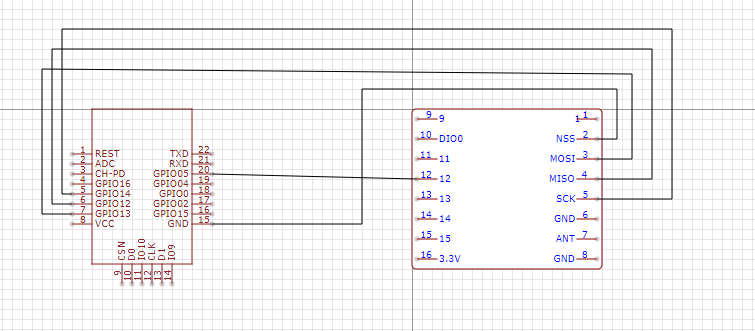
If I use the RFM69W to receive the door bell then the Data that comes out the data pin (pin 12 - DIO2) is not correct. I again use an esp8266 and connect it using the attached diagram and you can see the code I use for it in my first post. This code is not complete yet as I have not been able to write the code to decode the signal as the signal is not correct (as can be seen in the image I attached in my first post).

By partially using the library I just mean all I use the library for is getting the addresses and values for sending to the registers of the RFM69W. Everything else is done by my code.

Presumably there would be no need to write much new code if the data signal was the same.

The RFM69W has not been set up correctly, so whatever it puts out on its data line is not correct.

Your waveform pictures are too fuzzy, I tried to see if it was looking some kind of low-level encoding scheme using the wrong lens, so to speak.

I'm tapped out here - it seems like an RFM69W set up problem. If indeed the claim is that the demodulated but still coded data stream is actually made available on DI02. It is seeing something, just mangling it in an attempt to fix it for you as you have implicitly or directly told it.

BTW what is against just using the RBX6? I know I don't like the cheap dump Rx/Tx units, but they are easier to work with if you are getting down in the mud with them as you had to in the full code for it that you posted.

Simpler and more WYSIWYG.

a7

Yes you are correct, I would not need much new code once the data signal was the same.

Yes agreed that the RFM69 is not setup correctly, that is what I am looking for help to get the RFM69 configured correctly.

Strange the waveform pictures are two fuzzy they are clear this end. I could upload a more zoomed in or zoomed out image if that helps?

Haha, I knew you were going to ask why I do not just use the RXB6, the answer is I have further plans for this setup which requires the RFM69 as I want to be able to transmit other devices and receive a FSK signal (not at the same time) as well. I guess I could maybe somehow connect both devices in my final setup but I am hoping somebody will be able to get the RFM69 working.

Thanks for your help.

Murray

So you have some sort of undisclosed communications project which is only possible with the RFM69 ?

Possibly if you were to study the detailed operation of the RFM69 long enough you might make it work outside its normal area of operation, for your project, but it might be easier to re-think the project.

Yes, just other devices like the oregon temperature sensor and watchman oil sensor I want to detect too. However I am trying to get this working first.

I can tell you I have studied the manual for the RFM69 allot. I have been trying to get this working for several months now I am hoping I am just missing some setting or tweak in the config to get this working. Looking at the spec and the fact that the RFM69 is definitely picking up the transmission (just not demodulating it correctly) I feel it should be possible otherwise I would of already moved onto another way to try and achieve this.

Murray

There's a few ways to go, no shame in my opinion to using a radio meant for it on each stray RF transmitter / protocol thing you have deployed. With its own processor, yeah, sounds like fun.

It certainly seems like you should be able to grab the doorbell, which is what you've been saying it finally sinks in here, but You're not wasting time reading the RFM69W manual even if you only use it for more common things.

I wonder if SDR software defined radio would be a better single thing to get good at.

So much technology, so little time.

a7

what would happen if you mapped rssi to dio0 and compared that to the tx signal ?
the output you have now is almost like its trying to decode manchester recovered clock or something

This topic was automatically closed 120 days after the last reply. New replies are no longer allowed.