RGB LED Coding help

I have been trying to build a RGBW led controller that uses pots right now but i would like to move over to photoresistors for the project i have. I want to take the colors of light outside and reproduce them inside with white as well.

I got it to work with RGB, but when i went to add the White channel i broke it somehow. I dont know much about writing the code but i can read it. I would like to add a pot to control all channels as a dimmer as well.

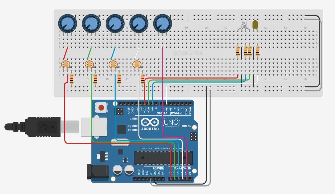
Can someone help me with the code please. Here is the code i have and a layout of what i have so far

const int analogPOTinRED = A0;
const int analogPOTinGREEN = A1;
const int analogPOTinBLUE = A2;
const int analogPOTinWHITE = A3;
const int analogPOTinALL = A4;

const int DigitalLEDoutRED = 11;
const int DigitalLEDoutGREEN = 10;
const int DigitalLEDoutBLUE = 9;
const int DigitalLEDoutWHITE = 6;

int PotValueRED = A0;
int PotValueGREEN = A1;
int PotValueBLUE = A2;
int PotValueWHITE = A3;
int PotValueALL = A4;

int LedValueRED = 11;
int LedValueGREEN = 10;
int LedValueBLUE = 9;
int LedValueWHITE = 6;

void setup() {
 Serial.begin(9600);
}

void loop() {
 PotValueRED = analogRead(analogPOTinRED);
 PotValueGREEN = analogRead(analogPOTinGREEN);
 PotValueBLUE = analogRead(analogPOTinBLUE);
 PotValueWHITE = analogRead(analogPOTinWHITE);
 PotValueALL = analogRead(analogPOTinALL);

 PotValueRED = map(PotValueRED, 0, 1023, 0, 255);
 PotValueGREEN = map(PotValueGREEN, 0, 1023, 0, 255);
 PotValueBLUE = map(PotValueBLUE, 0, 1023, 0, 255);
 PotValueWHITE = map(PotValueWHITE, 0, 1023, 0, 255);

 analogWrite(analogPOTinRED, DigitalLEDoutRED);
 analogWrite(analogPOTinGREEN, DigitalLEDoutGREEN);
 analogWrite(analogPOTinBLUE, DigitalLEDoutBLUE);
 analogWrite(analogPOTinWHITE, DigitalLEDoutWHITE);

 Serial.print("\t POT RED = ");
 Serial.print(analogPOTinRED);
 Serial.print("\t POT GREEN = ");
 Serial.print(analogPOTinGREEN);
 Serial.print("\t POT BLUE = ");
 Serial.print(analogPOTinBLUE);
 Serial.print("\t POT WHITE = ");
 Serial.print(analogPOTinWHITE);
 Serial.print("\t POT ALL = ");
 Serial.print(analogPOTinALL);
 
 Serial.print("\t LED RED = ");
 Serial.println(DigitalLEDoutRED);
 Serial.print("\t LED GREEN = ");
 Serial.println(DigitalLEDoutGREEN);
 Serial.print("\t LED BLUE = ");
 Serial.println(DigitalLEDoutBLUE);
 Serial.print("\t LED WHITE = ");
 Serial.println(DigitalLEDoutWHITE);

 delay(2);
}

Please use code tags (</> button on the toolbar) when you post code or warning/error messages. The reason is that the forum software can interpret parts of your code as markup, leading to confusion, wasted time, and a reduced chance for you to get help with your problem. This will also make it easier to read your code and to copy it to the IDE or editor. Using code tags and other important information is explained in the How to use this forum post. Please read it.

Please explain exactly what you mean by "i broke it".

my code worked when it was just RGB, before I added the W channel. I did not change anything, just copied the B code and changed it to W and it stopped working. I tried removing the W channel and it still did not work. I'm not sure what I did but i did not do it correctly

I worked on it some more and I found that you can't use names as I did for the different things, there is a system to naming the things that are connected. I rewrote the code and i came up with this. I still can't find out a way to get 'ALL' (The right most pot) to lower the values of the others (RGBW) equally like a normal dimmer without changing the colors produced. That is the part I need help with now, I have no clue what to do from this point.

const int analogInPinRED = A0;
const int analogInPinGREEN = A1;
const int analogInPinBLUE = A2;
const int analogInPinWHITE = A3;
const int analogInPinALL = A4;

const int analogOutPinRED = 11;
const int analogOutPinGREEN = 10;
const int analogOutPinBLUE = 9;
const int analogOutPinWHITE = 6;
const int analogOutPinALL = 3;

int sensorValueRED = 0;
int sensorValueGREEN = 0;
int sensorValueBLUE = 0;
int sensorValueWHITE = 0;
int sensorValueALL = 0;

int outputValueRED = 0;
int outputValueGREEN = 0;
int outputValueBLUE = 0;
int outputValueWHITE = 0;
int outputValueALL = 0;

void setup() {
  Serial.begin(9600);
}

void loop() {
  sensorValueRED = analogRead(analogInPinRED);
  sensorValueGREEN = analogRead(analogInPinGREEN);
  sensorValueBLUE = analogRead(analogInPinBLUE);
  sensorValueWHITE = analogRead(analogInPinWHITE);
  sensorValueALL = analogRead(analogInPinALL);
  
  outputValueRED = map(sensorValueRED, 4, 679, 0, 255);
  outputValueGREEN = map(sensorValueGREEN, 4, 679, 0, 255);
  outputValueBLUE = map(sensorValueBLUE, 4, 679, 0, 255);
  outputValueWHITE = map(sensorValueWHITE, 4, 679, 0, 255);
  outputValueALL = map(sensorValueALL, 1023, 0, 0, 255);
  
  analogWrite(analogOutPinRED, outputValueRED);
  analogWrite(analogOutPinGREEN, outputValueGREEN);
  analogWrite(analogOutPinBLUE, outputValueBLUE);
  analogWrite(analogOutPinWHITE, outputValueWHITE);
  analogWrite(analogOutPinALL, outputValueALL);

  Serial.print("sensor = ");
  Serial.print(sensorValueRED);
  Serial.print(sensorValueGREEN);
  Serial.print(sensorValueBLUE);
  Serial.print(sensorValueWHITE);
  Serial.print(sensorValueALL);
  Serial.print("\t output = ");
  Serial.println(outputValueRED);
  Serial.println(outputValueGREEN);
  Serial.println(outputValueBLUE);
  Serial.println(outputValueWHITE);
  Serial.println(outputValueALL);

  delay(500);
}

You are going to want to adjust the value of outputValueRED, outputValueGREEN, outputValueBLUE, and outputValueWHITE according to the value of sensorValueALL. So from reading your code it appears that if analogRead(analogInPinALL) == 0 you want all those values to remain unchanged, if analogRead(analogInPinALL) == 1023 you want all those values to be set to 0. If analogRead(analogInPinALL) == 511 you would want them to be divided by two. This idea of analogOutPinALL is completely wrong, you don't do this with hardware, you do it with code. Once you understand that writing the code should be easy enough.

Now, after doing that you may find it's not quite so simple because the eye doesn't perceive light in a linear fashion. The jump in brightness between 1 and 2 is much larger than between 1022 and 1023. There is some good information on working around this available but get it working with a linear adjustment first before deciding if more complex code is required.

I you map the ALL reading to a value below 256, you can use it as the upper limit on the channels.

This should work

const byte analogInPinRED = A0;
const byte analogInPinGREEN = A1;
const byte analogInPinBLUE = A2;
const byte analogInPinWHITE = A3;
const byte analogInPinALL = A4;

const byte analogOutPinRED = 11;
const byte analogOutPinGREEN = 10;
const byte analogOutPinBLUE = 9;
const byte analogOutPinWHITE = 6;
const byte analogOutPinALL = 3;

void setup() {
  Serial.begin(250000);
}

void loop() {
  int sensorValueRED = analogRead(analogInPinRED);
  int sensorValueGREEN = analogRead(analogInPinGREEN);
  int sensorValueBLUE = analogRead(analogInPinBLUE);
  int sensorValueWHITE = analogRead(analogInPinWHITE);
  int sensorValueALL = analogRead(analogInPinALL);

  // ALL defines the maximum possible value for each component
  byte outputValueALL = map(sensorValueALL, 0, 1023, 0, 255);

  byte outputValueRED = map(sensorValueRED, 0, 1023, 0, outputValueALL);
  byte outputValueGREEN = map(sensorValueGREEN, 0, 1023, 0, outputValueALL);
  byte outputValueBLUE = map(sensorValueBLUE, 0, 1023, 0, outputValueALL);
  byte outputValueWHITE = map(sensorValueWHITE, 0, 1023, 0, outputValueALL);

  analogWrite(analogOutPinRED, outputValueRED);
  analogWrite(analogOutPinGREEN, outputValueGREEN);
  analogWrite(analogOutPinBLUE, outputValueBLUE);
  analogWrite(analogOutPinWHITE, outputValueWHITE);

  printMapping(F("all"), sensorValueALL, outputValueALL, true);
  printMapping(F("red"), sensorValueRED, outputValueRED, true);
  printMapping(F("green"), sensorValueGREEN, outputValueGREEN, true);
  printMapping(F("blue"), sensorValueBLUE, outputValueBLUE, true);
  printMapping(F("white"), sensorValueWHITE, outputValueWHITE, false);
  Serial.println();
  delay(500); // debug only
}

void printMapping(const __FlashStringHelper* itsName, int inValue, byte mapValue, bool withComma) {
  Serial.print(itsName);
  Serial.write('(');
  Serial.print(inValue);
  Serial.print(F(")="));
  Serial.print(mapValue);
  if (withComma) {
    Serial.print(F(", "));
  }
}
all(410)=102, red(459)=45, green(451)=44, blue(427)=42, white(407)=40
all(399)=99, red(415)=40, green(421)=40, blue(408)=39, white(395)=38
all(393)=97, red(407)=38, green(414)=39, blue(402)=38, white(389)=36
all(390)=97, red(401)=38, green(409)=38, blue(398)=37, white(387)=36
all(391)=97, red(400)=37, green(408)=38, blue(399)=37, white(388)=36
all(394)=98, red(403)=38, green(412)=39, blue(402)=38, white(392)=37
all(395)=98, red(404)=38, green(413)=39, blue(404)=38, white(394)=37
all(394)=98, red(403)=38, green(412)=39, blue(403)=38, white(393)=37

Thank you very much Whandall, I did not think of using the outputValueALL as a variable. And the Serial debug is a lot nicer than what I had. The AnalogOutPinALL = 3, that pot does not need a output pin for data, would it be good to remove that part or does the code need that assigned to something?

GuardianFox:
The AnalogOutPinALL = 3, that pot does not need a output pin for data, would it be good to remove that part or does the code need that assigned to something?

You can safely remove that, I just forgot it.

Is the effect now like you want to have it?

It does work as I was hoping thank you again. As a second project I'm glad there are people to help.