I got two phones so while I'm waiting on other parts I thought I'd try to see what the impedance of the coils are so that I can size my PSUs.
I thought i'd try measure them by seeing how the voltage of a sine wave drops over them at different frequencies using this method - https://www.youtube.com/watch?v=iQQe8uSZ8xc - and a USB oscilloscope that I have.
Strangely though I'm not getting any voltage drop across the coils.
i.e. when I connect the coil to the signal generator I get no change to the recorded sine wave. If iI connect a resistor across I do. this is the same at the various frequencies I've tried.
I'm wondering what obvious thing I'm missing? Any help much appreciated.
Edit -
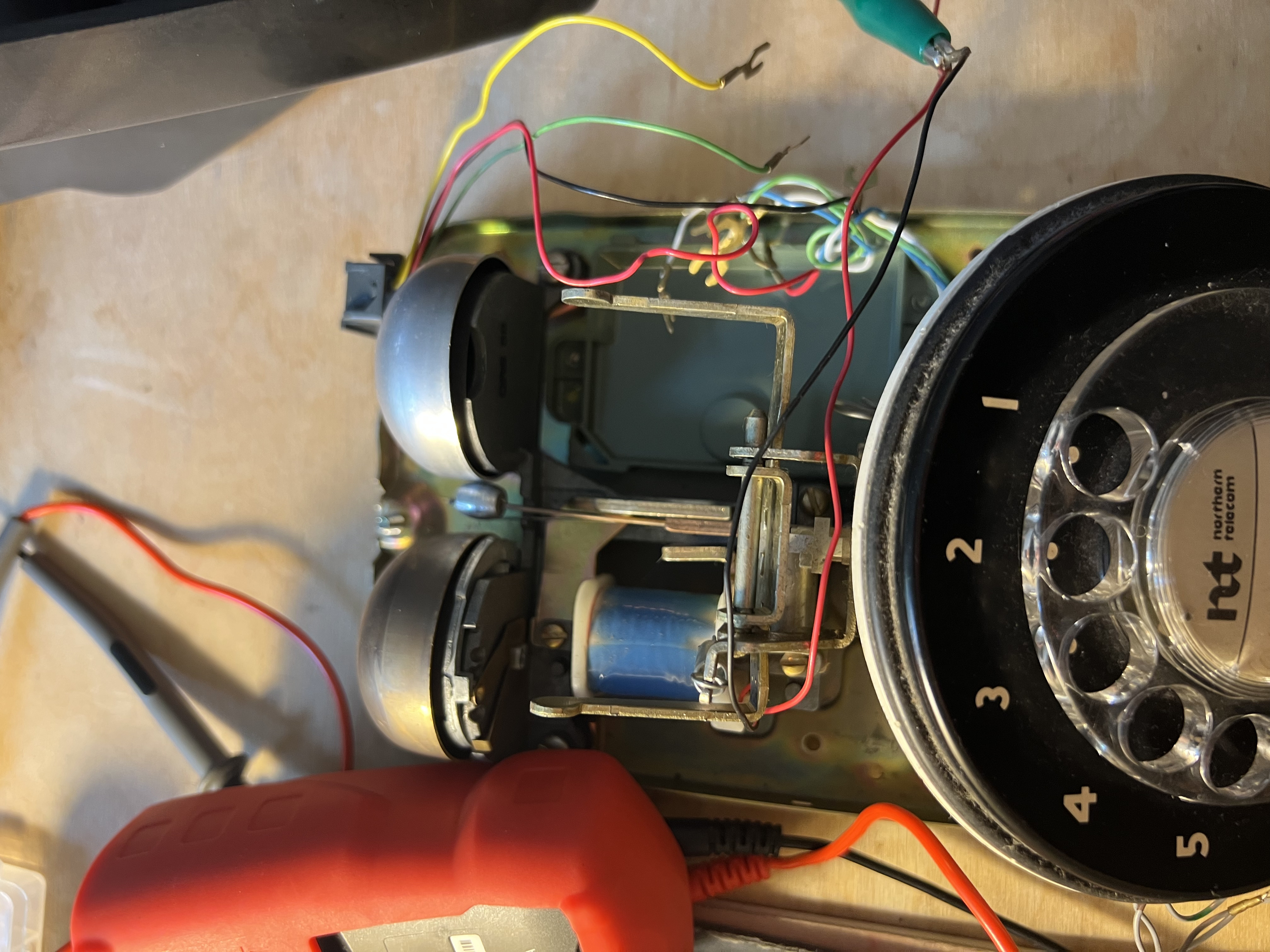
I should note that in the top picture I'm connecting across the two red wires connected to the coil beside the bell striker.
In the second picture I'm connecting to the red and black wires across the blue coild
Get one or two door bell transformers. Try ringing with only one transformer. Then wire the transformer secondaries in series to get 48 VAC and try that.
I should have the other parts in the next few days so it doesn't make sense to get other parts.
I guess I'll just get the parts and try out some PSUs and see how they go - can't seem to measure the inductance.
You can get a boost converter and a double pole double throw and generate the ring, that how it was in the CO (Central Office). Note these relays were designed for this type of application. Do not expect much below 50V.
The part missing on the top and the thing with all the screws on the bottom is the network I was referring to.
If you got across a phone line when it was ringing you got a good zap.
Consider the bells are an electric motor with the armature moving back and forth rather than a circular motion. The power required to ring the bells will be similar to powering a small electric motor with AC.
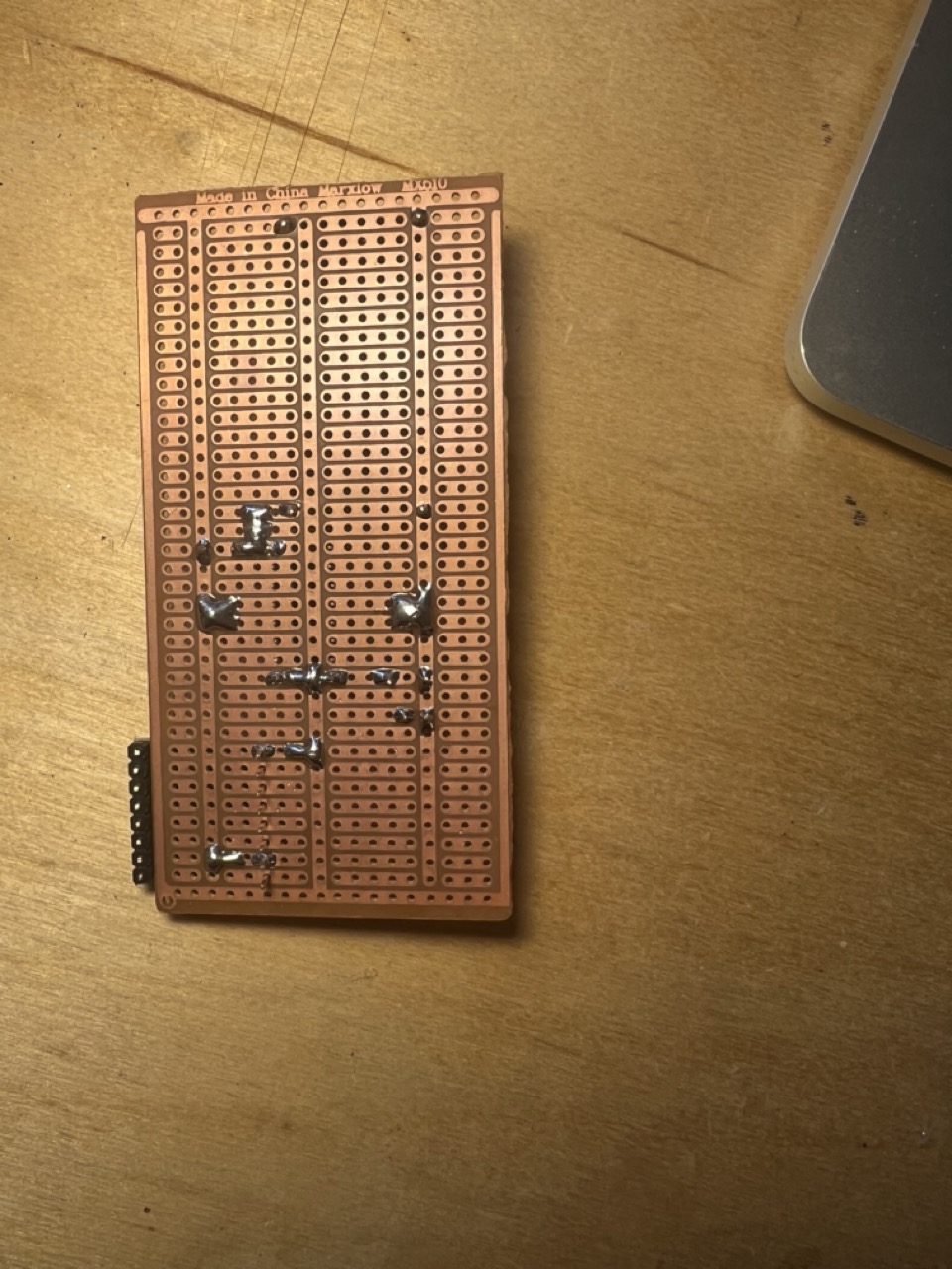
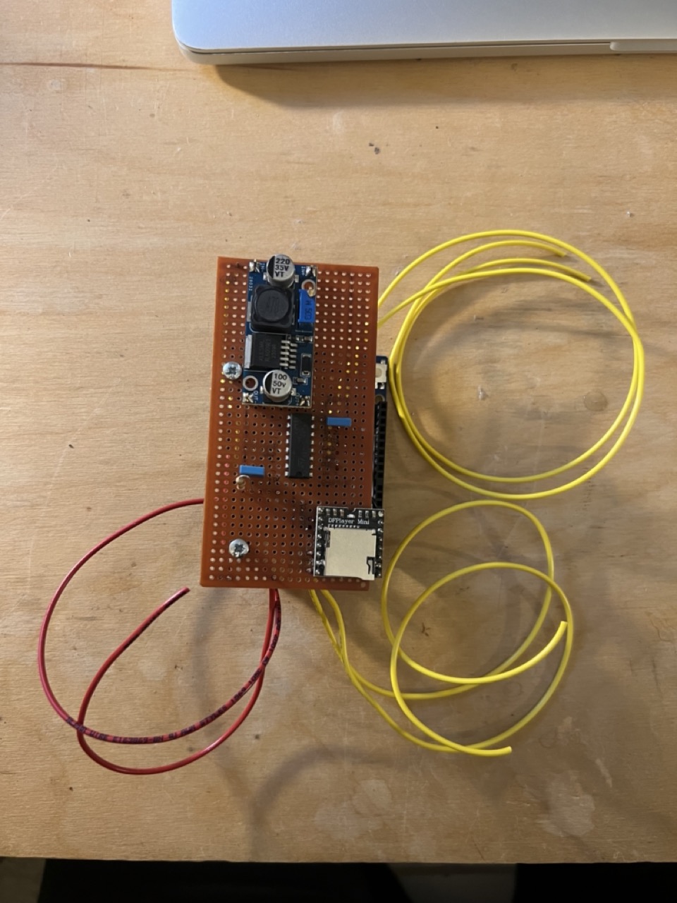
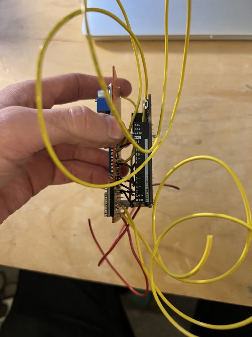
Here's some images of the ringing system and mp3 module for playing audio.
Is tested and working (can't upload video but it goes drrrring!)
Yellow cables for speaker and ringer, red cables for hook - power not hooked up here.
Hi Would you be willing to build and sell me two of these units, set up to be powered by USB or 12 v power (your choice) and triggered by a PIR? We would like it set to only accept a trigger every 5 minutes, or ideally be adjustable with a delay range.
I don't build hardware like this except for my own use, however, what you can do is put a request into this corner of the forum which is intended for paid jobs: Jobs and Paid Consultancy - Arduino Forum and hopefully you find someone to build it for you. The code and schematics are complete and, if someone does have a problem with it after building, they can simply ask for help in this thread. One thing to note is that it was designed for battery operation and it can be considerably simplified if low power consumption is not a requirement. The maximum voltage of that design is 36 volts and this may not be suitable for all telephones. The addition of a PIR sensor would be an extra.