ROM-Reader for Super Nintendo / Super Famicom Game Cartridges

skaman:
I managed to dump the SA-1 cart.

Wow - congratulations once again! :o There are not many solutions out there that support all the enhancement chips... :slight_smile:

skaman:
The CIC-SA1 connection is a bit hit-or-miss right now. Most of the time it doesn't connect but it will eventually work. I think I have to tweak the reset timings to get it working more consistently.

I guess, you have already seen this, but there was some discussion in the nesdev.com forums about this - just search for "ripping sa1 nesdev" in Google...

Best regards
Michael

Some notes on the CIC stuff.

The most compatible version of the lock seems to be the snesCIC. I've been getting the best results using the snescic-lock-resync version. Get the ASM & HEX here: sd2snes/cic at develop · mrehkopf/sd2snes · GitHub

;   snesCIC LOCK 12F629
;   pin configuration: (cartridge slot pin) [original 18-pin SMD lock CIC pin]
;
;                       ,---_---.
;      +5V (27,58) [18] |1     8| GND (5,36) [9]
;      CIC clk (56) [7] |2     7| CIC data i/o 0 (55) [1]
;   host reset out [10] |3     6| CIC data i/o 1 (24) [2]
; CIC lock reset in [8] |4     5| CIC slave reset out (25) [11]
;                       `-------'

You wire up the snesCIC to the Cart Pins 24, 25, 55, 56. Connect CIC Pin 2 and Cart Pin 56 both to the clock generator outputting 3.072MHz. I also connected Host Reset (CIC Pin 3) and CIC Lock Reset (CIC Pin 4) to available pins on the Mega 2560.

The snesCIC has specific timing built into the code for the CIC LOCK-KEY to work. We need to set up our code to make sure the LOCK-KEY works right. Since the snesCIC has the correct timing, we need to trigger the code at the right time using the CIC Lock Reset. When CIC Lock Reset is HIGH then it is in reset, when LOW it is running the CIC code.

In our Arduino setup(), we immediately set CIC Lock Reset HIGH otherwise the LOCK-KEY communication may fail. Pulling CIC Lock Reset HIGH gives us time to get everything else that is connected to the Arduino up and running before trying the CIC handshake. We let most everything initialize in setup() then we set CIC Lock Reset LOW to start the CIC code and hopefully get a valid connection to the cart.

After making the changes to setup(), the SA-1 carts get recognized most of the time now. For when the cart is not recognized, I added a soft_Reset() "jmp 0" to reset the reader and start over. I've dumped all of my SA-1 carts except for one problem cart, PGA European Tour. I don't know what is different about the cart but it only spits out 0x17s right now.

EDIT: I managed to get the problematic PGA European Tour to dump. I put the cart in the SNES and let it run for a little bit then moved it over to the reader and dumped it. I'm still not sure what makes this cart fail. I'll have to look at the SA-1 registers to see what is there.

Success!

I finally fixed the S-RTC communication and have the S-RTC outputting the time correctly. So both the RTC and S-RTC now output properly. If anyone thinks it would be worthwhile to add writing the time to the RTC chips, then let me know. I'm not inclined to add it as the time can always be set in the respective cart.

I've made progress on a different cart. I managed to get the games off the Nintendo Power (SF Memory Cassette) cart in multi-game configuration. It requires some fiddling with the MX15001TFC registers 0x2400 and 0x2401.

In single game configuration (with or without the Menu), the reader should be able to see the game data in banks 00-7F in LoROM (0x8000-0xFFFF). After dumping the Menu, the game data will be at 0x80000 in the dump. If you set the registers to switch to the game, then the data changes and the cart actually becomes the individual game and the normal cart dumping process will work.

I have a multi-game (3-in-1) cart and the games are not visible to the reader. Only the Menu is visible and it repeats 8x (in banks 00-7F). I searched all of the banks and there is no game data to be found. The MX15001TFC hides the actual game data. Accessing the game data requires setting registers 2400 and 2401, the data changes for each game so it requires multiple steps to dump all of the games.

Right now I can dump individual game data with the settings hardcoded but it will take some time to code it so that the reader can dynamically dump the games. I have to wrap my head around coding all of this because of the number of steps involved. We need to access the Menu, read the game entries, set the correct registers, dump the individual game data, then reset the cart to repeat the process to dump the next game.

I have to experiment more with switching between games. Registers 2400 and 2401 remain active even when acting as a single game so I'm hoping it is possible to switch between the games with a reset instead going back to the Menu.

Ok. So I appear to have sorted out the last inconsistency issue with the SA-1 carts. The key is getting the clock signals exactly right in order to have the cart recognized and dump properly. One of my SA-1 carts, PGA European Tour, almost never got recognized due to a slightly incorrect clock frequency. I completely forgot that I had an old PIC 16F84 frequency counter so I never bothered to check the clock signals until yesterday.

Using the Si5351 Arduino library (GitHub - etherkit/Si5351Arduino: Library for the Si5351 clock generator IC in the Arduino environment), there is a calibration needed to get the clock output as close as possible to the target 21.477272 MHz and 3.072 MHz. If you read the documentation on the library, then you will find the calibration section in the Readme. You need to run the si5351calibration sketch in the Arduino IDE to find the setting for your individual setup.

After testing my clock generator with a frequency counter, I found that my clocks were at 21.46998 MHz and 3.07096 MHz. So the clock generator definitely needed calibration. I ran the si5351calibration sketch in the IDE and found the correction needed for my reader. The set_correction value needs to be set early in the setup. Here's how my clock generator section in setup() looks right now:

void setup() {
...
  // Adafruit Clock Generator
  clockgen.set_correction(-29000); // Find this value by using the si5351calibration in the Arduino IDE
  clockgen.init(SI5351_CRYSTAL_LOAD_8PF, 0);
  clockgen.set_pll(SI5351_PLL_FIXED, SI5351_PLLA);
  clockgen.set_pll(SI5351_PLL_FIXED, SI5351_PLLB);
  // Set Clock Generator CLK0 to 21.477272MHz
  clockgen.set_freq(2147727200ULL, SI5351_PLL_FIXED, SI5351_CLK0);
  // Set Clock Generator CLK2 to 3.072MHz
  clockgen.set_freq(307200000ULL, SI5351_PLL_FIXED, SI5351_CLK2);
  clockgen.output_enable(SI5351_CLK0, 1);
  clockgen.output_enable(SI5351_CLK1, 0);
  clockgen.output_enable(SI5351_CLK2, 1);
...
}

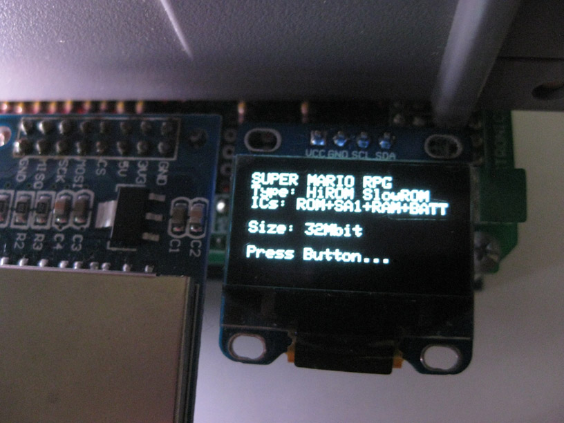
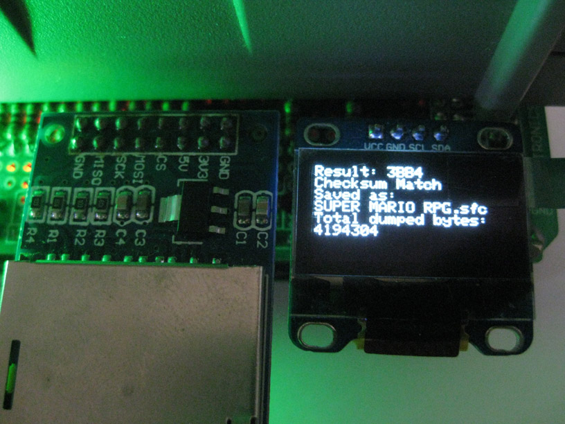
The clocks are now almost spot on at 21.47727 MHz and 3.07199 MHz. With the current clock settings, the SA-1 carts are recognized every time even the problem PGA European Tour cart. I'll be picking up a new frequency counter to replace my old PIC16F84 unit so maybe I can get the clocks exactly right.

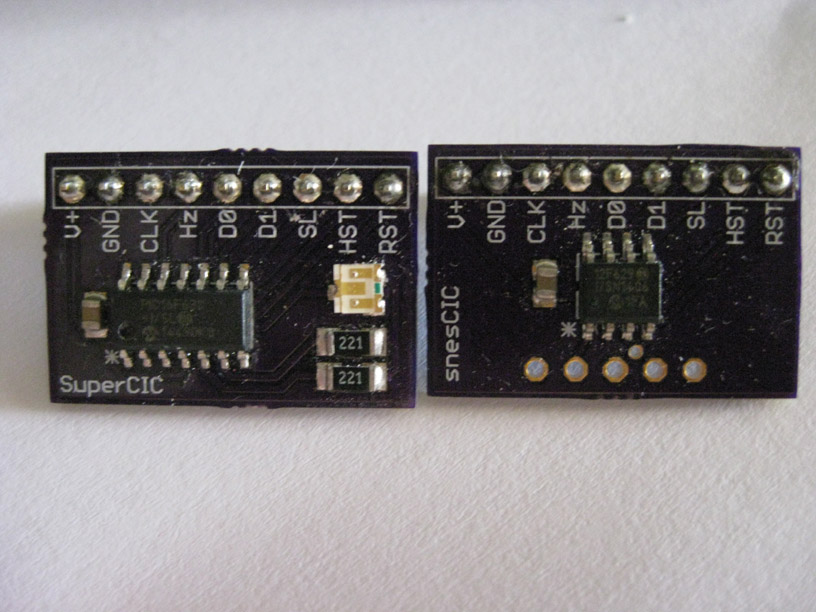
For anyone planning on adding SA-1 support to their reader, the snescic-lock-resync is definitely the best version to use. Don't bother with the SuperCIC as it doesn't recognize the SA-1 carts as reliably as the snesCIC resync version.

Using my reader, I dumped a new version of an SA-1 cart, PGA Tour 96 (U). The cart that I dumped is Revision 1.1 with ROM chip "SNS-A3GE-1". The previous known version is Revision 1.0 with chip "SNS-A3GE-0" (I dumped a copy of that one too). I submitted the new dump to No-Intro and GoodTools so it will eventually be available for anyone that cares about this type of stuff.

Nice work, sanni!

I'll have to post a complete version of my reader code. The reader code should support all of the enhanced chip carts. I was hoping to include full support for the Nintendo Power (SF Memory Cassette) carts but the NP carts are finicky (even more than the SA-1 carts). If I can't manage to get the NP cart working 100%, then I'll post a version with everything but the NP code.

The biggest problem I'm having with the NP carts is I cannot consistently get the cart to switch to a single game. Switching to a single game is important as that is the only way to see and dump the SRAM. Once the cart becomes a game, then the processor will map the savegame to the normal SRAM location. I've written all of the code even added a menu for the multi-game but the timing on getting the cart to switch is hit-or-miss. I've dumped all of my NP carts but it takes multiple tries to get each game done.

I also have to do more testing as I recently got a NP cart with a combination of LoROM and HiROM games and I want to confirm the mapping for the HiROM game. It appears that the HiROM game is mapped like a LoROM game including the SRAM. I'll have to do more testing to be sure.

I tried to figure out the pinout of a Nintendo Power cart, maybe you find it useful. There might be still some errors left in the schematics though.

skaman:
Nice work, sanni!

I'll have to post a complete version of my reader code. The reader code should support all of the enhanced chip carts. I was hoping to include full support for the Nintendo Power (SF Memory Cassette) carts but the NP carts are finicky (even more than the SA-1 carts). If I can't manage to get the NP cart working 100%, then I'll post a version with everything but the NP code.

The biggest problem I'm having with the NP carts is I cannot consistently get the cart to switch to a single game. Switching to a single game is important as that is the only way to see and dump the SRAM. Once the cart becomes a game, then the processor will map the savegame to the normal SRAM location. I've written all of the code even added a menu for the multi-game but the timing on getting the cart to switch is hit-or-miss. I've dumped all of my NP carts but it takes multiple tries to get each game done.

I also have to do more testing as I recently got a NP cart with a combination of LoROM and HiROM games and I want to confirm the mapping for the HiROM game. It appears that the HiROM game is mapped like a LoROM game including the SRAM. I'll have to do more testing to be sure.

Will it include the saving and writing of SRAM (your completed work)? Thanks for your efforts!

Dumping the SRAM on the NP cart is definitely possible. I've dumped all the savegames off of my NP carts.

For a single game NP cart, then the SRAM should be visible.

For a multi-game NP cart, you need to enter the command sequence to set the cart to a game then the corresponding savegame becomes accessible in the SRAM.

I haven't tried to write the SRAM yet. I'll have to give it a try sometime.

I'm waiting on a bunch of NP carts to arrive from Japan to do more testing on.

Anyway you could release the code you have up to now and maybe give us an update when you got the NP carts all figured out? I'd love to build me one of these with your code and maybe even make a custom PCB for this project.

Here's the code with support for the Enhanced chip carts for sanni's cart reader:

I've included the SDFat library with long filename support and the Si5351 library for the Adafruit Clock Generator. If this is your first build, then you'll also need the other libraries that sanni included (LCD, RGB, DigitalIO).

A few notes on the hardware modifications:

The Adafruit Clock Generator is needed for SPC7110 and SA-1 carts. The clock generator uses CLK0 to generate the 21.477272MHz master clock signal that is connected to Pin 1 of the cart connector. CLK2 outputs the 3.072MHz CIC clock signal which is wired to the CIC clk in on the snesCIC/SuperCIC chip.

The snesCIC/SuperCIC has the CIC host reset and CIC lock reset connected to Arduino pins 6 & 7, respectively (although I haven't implemented any code for the CIC host reset in this version). The remaining CIC connections are wired to the appropriate pins on the cart connector.

As of right now, the snesCIC/SuperCIC is only really necessary for SA-1 carts. There's a possibility that the Nintendo Power (SF Memory Cassette) carts need the CIC but my best results with my current NP code is without the CIC (and clock).

One last item, some of these enhanced chip carts are extremely sensitive to how the power is supplied. If a cart is not being recognized, then check your power supply and/or try a different connection.

I forgot to specify that we use the snesCIC/SuperCIC LOCK code.
snesCIC resync lock: sd2snes/snescic-lock-resync.asm at develop · mrehkopf/sd2snes · GitHub
snesCIC resync lock (HEX): sd2snes/snescic-lock-resync.hex at develop · mrehkopf/sd2snes · GitHub
SuperCIC lock: sd2snes/supercic-lock.asm at develop · mrehkopf/sd2snes · GitHub

Please post any improvements made to the code.

Good luck!

Pictures of the snesCIC/SuperCIC. Sorry for the dust!

I've made a pcb for it, since I didn't want to rewire my old build for adding the full lenght slot. It should arrive in 2 weeks time. Well worth the saved time compared to wiring everything per hand.

If you have a closer look you will notice that I changed all the pins around. This is so that the address and data lines are grouped together on one port which will in theory give an insane speed boost since you can just do:

PORTC = myData;

instead of:

void writeData(byte myData) {

  if ( (myData & 1) == 1 ) digitalWrite(d0Pin, 1); else digitalWrite(d0Pin, 0);
  if ( (myData & 2) == 2 ) digitalWrite(d1Pin, 1); else digitalWrite(d1Pin, 0);
  if ( (myData & 4) == 4 ) digitalWrite(d2Pin, 1); else digitalWrite(d2Pin, 0);
  if ( (myData & 8) == 8 ) digitalWrite(d3Pin, 1); else digitalWrite(d3Pin, 0);
  if ( (myData & 16) == 16 ) digitalWrite(d4Pin, 1); else digitalWrite(d4Pin, 0);
  if ( (myData & 32) == 32 ) digitalWrite(d5Pin, 1); else digitalWrite(d5Pin, 0);
  if ( (myData & 64) == 64 ) digitalWrite(d6Pin, 1); else digitalWrite(d6Pin, 0);
  if ( (myData & 128) == 128 ) digitalWrite(d7Pin, 1); else digitalWrite(d7Pin, 0);
}

Hi sanni,

Nice PCB. I might need one! I recently pulled a cart connector from a broken Retron 3 and it has the proper pin spacing.

One thing on the clock generator location, the USB connector on the Arduino is close to the pins for the clock generator on my current adapter. I put a layer of kapton tape over the USB connector to prevent a short (just in case). I also have some plastic spacers sandwiched in between the adapter and Arduino but it might be really close if you fully seat the adapter onto the Arduino.

Thanks!

I'll send you one, no problem. :slight_smile:

I tried to stay away from the USB socket but it still might conflict with the 6pin ISP header depending on the used Arduino board, but nothing a little tape or desoldering iron couldn't fix.

The manufacturer already emailed me an image of the order, I like the color.

As you can see I used the remaining board space for a little break-out board, just plug it into the cart slot and you got access to all the important pins to mess around with, e.g. when you want to use the arduino to program a 29F032 flashrom.

I just hope I didn't mess up and the board actually works :cold_sweat:

I'll take one of those bad boys if you're selling them, if you don't mind could you post your schematic? I also notice 2 SNESCIC in the images above, I can see one is the Pic16F30 but what is the smaller one used? Also which of the CIC codes is the one to use fr the project?

Sanni maybe you could add a Voltage Regulator or something else required so the Cart is powered correctly as it seems to be an issue for some games or rather the USB ports lack of power.

Are you guys using the MEGA 2560 R3 Board or something else? I'm about to buy all the parts needed but this is the only thing I'm unsure of. Thanks.

sanni's adapter interfaces with the Arduino MEGA 2560 R3.

As for the CIC, snesCIC Lock uses PIC12F629 and SuperCIC Lock uses PIC16F630. You can use either one. I've had better success with the snesCIC using the resync code that was linked to. I've tested both on my adapter as I built the boards to be interchangeable. sanni's new PCB is setup for the 12F629.

Good luck!

The Arduino Mega does have a 5V 1A power supply onboard that takes a 9-12V barrel plug type power supply. If you have both USB and the 9V-12V external power supply plugged in the Arduino will automaticly use the external supply for power instead the USB.

There are 3 different versions of the Arduino Mega 2560 that have different chips for USB communication:

  • the old official design with a FTDI chip
  • the new official design with an ATMEGA16U2
  • and an unofficial chinese redesign with a CH340

The unofficial chinese redesign is the cheapest but since you can also get a clone following the official design for about ~$10 (like ebay #360790082588) I would just buy that instead. Especially since all shields and cases are designed with the official design in mind.

Awesome! Thanks guys for the responses and looking forward to the eagle files as well. One last question on parts: What socket are you guys using or recommend (besides stripping it from an SNES or Retron)? I have found the ones mentioned by another user in this thread:

62pin= http://www.ebay.com/itm/131137330390
46pin= http://www.ebay.com/itm/131416146382

and from his comments they seem to work. Wondering what are your recommendations and what is the pitch of the SNES pins? I might try alibaba to see if there is some distributor with the official specs (once I know them).

Official ones are 2.5mm pin pitch. I have one from a Retrode and a short one from a HoneyBee Super Game Converter. Both also have the correct 2.5mm.

Any of the commonly available connectors with 0.1" (2.54mm) spacing will be off. For the center 46 pins, it doesn't matter too much. Once you get to the ends of the full length connector, the spacing will be noticeably off.

The Wonderco (Centronic) 46 pin connector listed on eBay will work but the spacing will be off. My adapter uses the 46 pin connector and I cut an extra connector to add the end section. I tried to shift the end section more into alignment when attaching it to the adapter.

The SNES Game Genie has a proper spaced 46 pin connector. The Retron 3 has a proper spaced full length connector. The later SNES consoles have thru-hole cart connectors - they're the ones with the black plastic mounting tabs on the end.

Good luck!