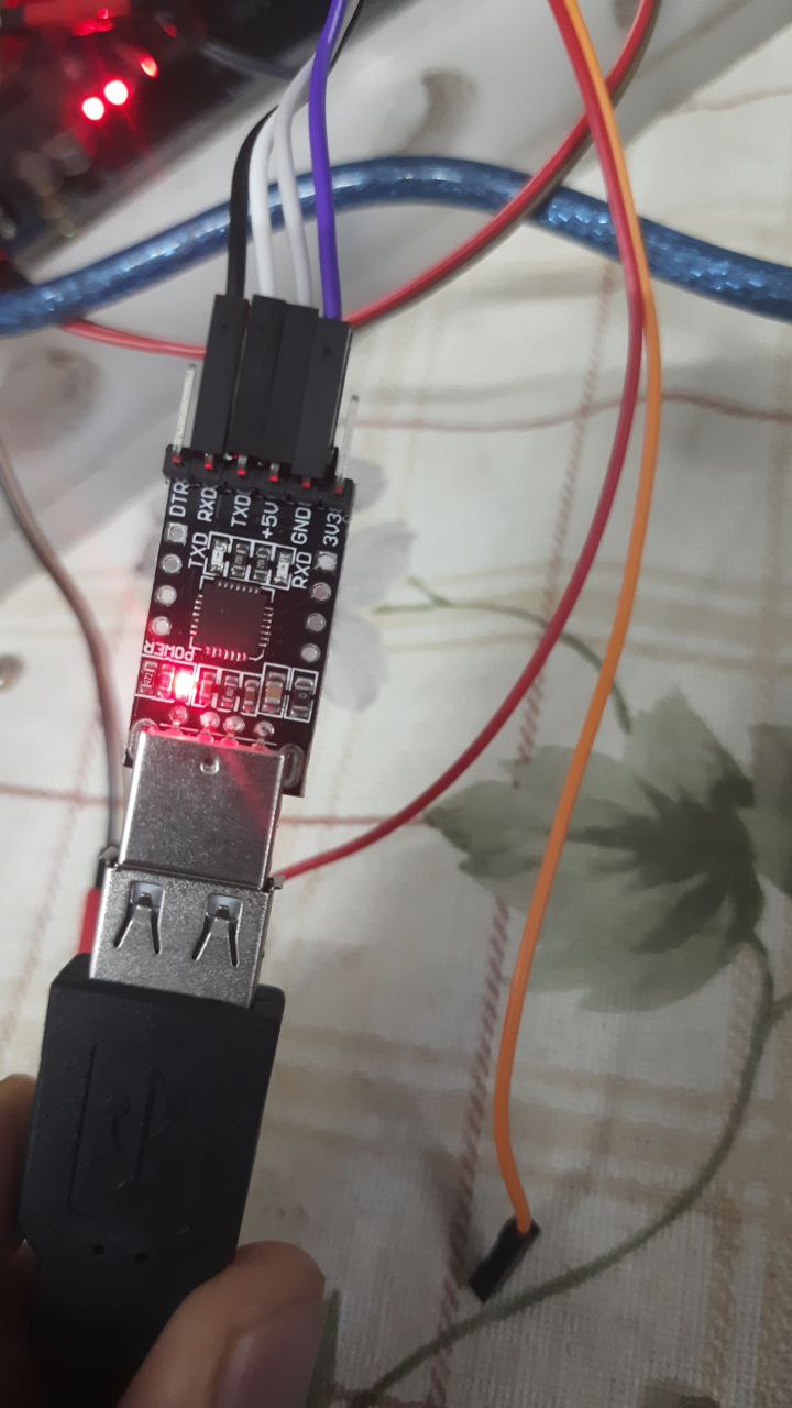
Actually I am using new version of rplidar a1m8-r6 with arduino mega connected to serial1 of it, circuit connection are as given below, SINCE NEW BOARD DOESN'T HAVE USUAL SPACERS BETWEEN PINS I AM USING THE TTL TO USB CONVERTER GIVEN ALONG WITH THE LIDAR, USING ANOTHER USB TO TTL CONVERTER, AND CONNECTING IN THE WAY GIVEN BELOW
#include <RPLidar.h>
#define RPLIDAR_MOTOR 3  // The PWM pin for control the speed of RPLIDAR's motor (MOTOCTRL).

RPLidar lidar;

void setup() {
  Serial.begin(115200);
  Serial1.begin(115200);  // For RPLidar
  lidar.begin(Serial1);
  pinMode(RPLIDAR_MOTOR, OUTPUT);  // set pin modes
  Serial.println("reached before serial");


  if (!lidar.begin(Serial1)) {
    Serial.println("Failed to initialize lidar!");
    while (1)
      ;
  }
  lidar.startScan();
  Serial.println("start scan run successfully");
}

float minDistance = 100000;
float angleAtMinDist = 0;

void loop() {
  Serial.println("entered loop");
  if (IS_OK(lidar.waitPoint())) {
    //perform data processing here...
    Serial.print("reached inside lidar.waitpoint");
    float distance = lidar.getCurrentPoint().distance;
    float angle = lidar.getCurrentPoint().angle;  // 0-360 deg

    if (lidar.getCurrentPoint().startBit) {
      // a new scan, display the previous data...
      printData(angleAtMinDist, minDistance);
      minDistance = 100000;
      angleAtMinDist = 0;
    } else {
      if (distance > 0 && distance < minDistance) {
        minDistance = distance;
        angleAtMinDist = angle;
      }
    }
  } else {
    analogWrite(RPLIDAR_MOTOR, 0);  //stop the rplidar motor
    // Try to detect RPLIDAR
    Serial.println("entered else condition, without checking lidar waitpoint");
    rplidar_response_device_info_t info;
    if (IS_OK(lidar.getDeviceInfo(info, 100))) {
      // Detected
      Serial.println("get device info run, succesfully");
      lidar.startScan();
      analogWrite(RPLIDAR_MOTOR, 255);
      delay(1000);
    }
  }
}

void printData(float angle, float distance) {
  Serial.print("dist: ");
  Serial.print(distance);
  Serial.print("    angle: ");
  Serial.println(angle);
}
once I start my serial monitor emits out this data
entered loop
reached before serial
start scan run successfully
entered loop
entered else condition, without checking lidar waitpoint
entered loop
entered else condition, without checking lidar waitpoint
entered loop
I am not able to get exact required data, what might be issue ? I am not sure if I have left out some important data for you to troubleshoot, please let me know if you need more data to answer, will be ready to give
Blockquote Provide both a clear picture and wiring diagram of that setup.
Blockquote
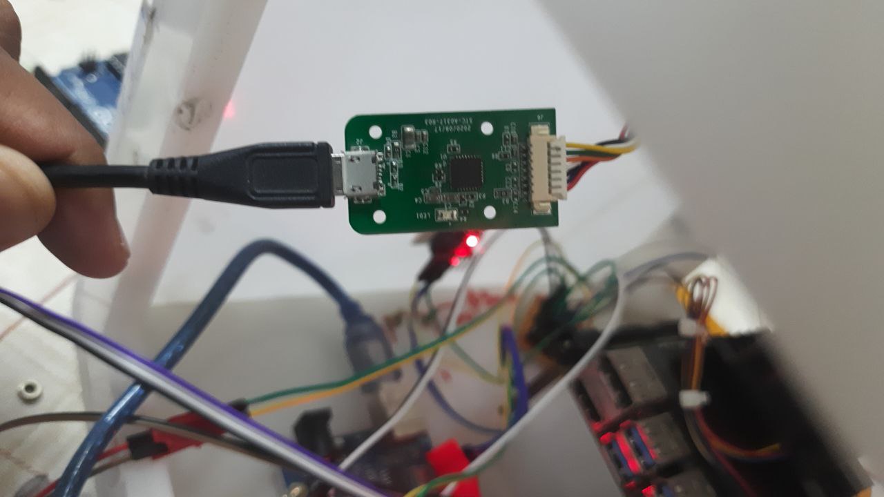
MORE details, this is the rplidar I am using click here, it comes with ttl to usb board with micro usb to usb male connectors, as I cannot directly use the pins as pins are really small, i am using female to female usb connector and then I connect to usb to ttl converter to connect to arduino mega, lidar is rotating once we connect, but no data transfer is happening
Blockquote it seems that communication started and then you handle something wrong or device is faulty.
do you can translate everything from Serial1 to Serial,
Blockquote
i am not able to communicate actually, i can't get any data from Serial 1, is this what you are asking?
If you're doing what I think (you have not yet provided a wiring diagram) that probably won't work. the USB to TTL converter likely must plug into a USB Host.
actually, rplidar has given its own ttl to usb converter, it uses cp2102 chip to convert to usb, and then after receiving through usb, I am using ch340g chip to convert from usb to ttl and then we are sending it to arduino, will there be an issue, due to this?
No, it's not. The external USB / UART converter that comes with it is a USB Slave. But the Lidar itself has UART Serial connections.
Unnecessary. @Siddique needs to figure out a way to connect from the Lidar's UART pins to the Arduino's. Perhaps construct or buy a custom cable. Worst case, cut off the connector that connects to the provided converter and connect the bare end of that cable to the Arduino's UART pins.
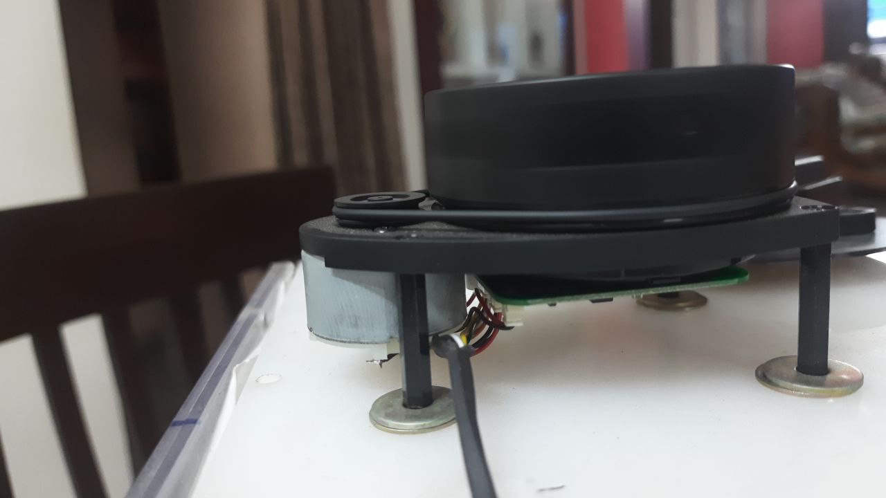
connected the lidar as per datasheet to Serial3 of arduino Mega by cutting the wires and rearranging this as shown in previous post circled like give away, lidar which has this datasheet datasheet being used
AND RP LIDAR A1M8 PROVIDES US WITH LIBRARY LIBRARY LINK
While using example program "simple connect" it doesn't emit correct data, comes up with random data, then I realized the code doesn't work for new version, if anyone could help me with interfacing this lidar with arduino mega connected to serial3, it would be of great help, have given correct datasheet for my product as older version is very popular in internet searches and also library runs good for older version and not new version, and this is the output from serial monitor from simple connect program
the code which I have modified from simple connect is this
// This sketch code is based on the RPLIDAR driver library provided by RoboPeak
#include <RPLidar.h>

// You need to create an driver instance
RPLidar lidar;

#define RPLIDAR_MOTOR 3 // The PWM pin for control the speed of RPLIDAR's motor.
                        // This pin should connected with the RPLIDAR's MOTOCTRL signal


void setup() {
  // bind the RPLIDAR driver to the arduino hardware serial
  lidar.begin(Serial3);
  Serial.begin(115200);
  //Serial.begin(115200)

  // set pin modes
  pinMode(RPLIDAR_MOTOR, OUTPUT);
}

void loop() {
  if (IS_OK(lidar.waitPoint())) {
    float distance = lidar.getCurrentPoint().distance; //distance value in mm unit
    float angle    = lidar.getCurrentPoint().angle; //anglue value in degree
    bool  startBit = lidar.getCurrentPoint().startBit; //whether this point is belong to a new scan
    byte  quality  = lidar.getCurrentPoint().quality; //quality of the current measurement
    Serial.print("distance: "); Serial.println(distance);
    Serial.print("angle: ");  Serial.println(angle);

    //perform data processing here...


  } else {
    analogWrite(RPLIDAR_MOTOR, 0); //stop the rplidar motor

    // try to detect RPLIDAR...
    rplidar_response_device_info_t info;
    if (IS_OK(lidar.getDeviceInfo(info, 100))) {
       // detected...
       lidar.startScan();

       // start motor rotating at max allowed speed
       analogWrite(RPLIDAR_MOTOR, 255);
       delay(1000);
    }
  }
}
LIDAR   -------------> ARDUINO MEGA

TX     -------------> 15(RX3 OF ARDUINO MEGA)
RX      -------------> 14
VCC_5V  -------------> 5V SUPPLY
GND     -------------> GND

GND_MOTO   -------------> GND
CTRL_MOTO   -------------> 3RD PIN OF ARDUINO MEGA
5V_MOTO         ------------->5V SUPPLY
I am struggling with this for the past 2 weeks to get the data out, this old post is the evidence of it, any help would be of great significance as far as I am concerned
data received is not accurate and it shows some random data, what might be the possible issue as, when I connect it to ros(rviz) 2d mapping is perfect, but not here, what could be the possible reason