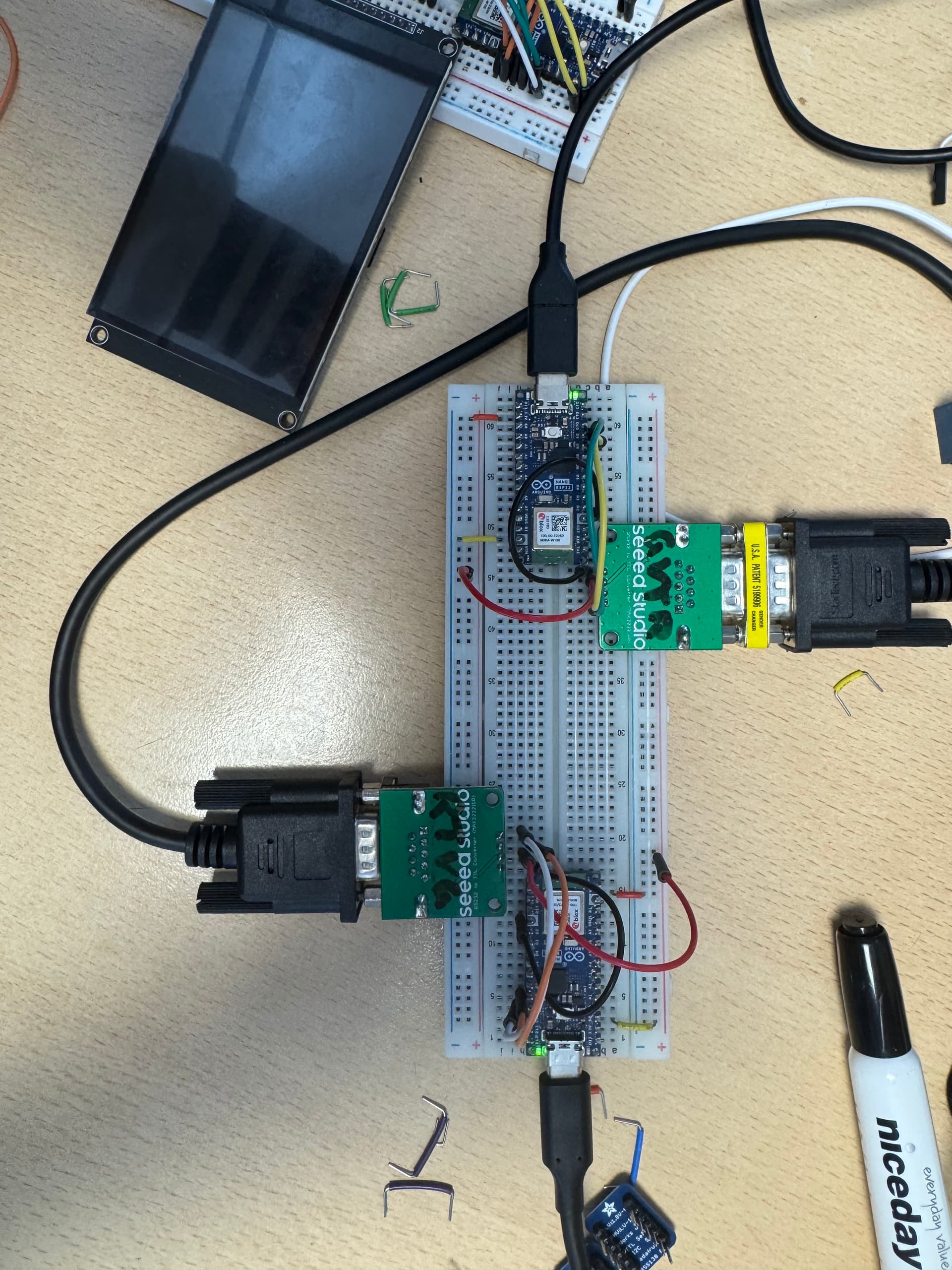
I have a DB9 Male to female cable with a male-male gender changer to connect the two MAX3232 IDR modules. D8 and D9 (GPIO 17 and 18) are UART 1 pins on the Arduino Nano ESP32, so I thought I could use these pins for communication. I'm sure I can use the MAX3232 with 3.3v as it can operate between 3v and 5v. I am not receiving any data from this. Can someone help me with this?
Hi,
How have you then connected the two MAX ICs.
TX to Rx and Rx to Tx?
Can you please post a copy of your circuit, a picture of a hand drawn circuit in jpg, png?
Hand drawn and photographed is perfectly acceptable.
Please include ALL hardware, power supplies, component names and pin labels.
This is pretty essential, a picture can save a thousand posts.
Yes they both compile and upload, and I have changed the IDE to use GPIO pin numbers instead, as I have had issues before in the past with using the arduino pin configuration
I am powering the receiver Nano ESP32 via USB through my PC so I can use the serial port. I am powering the other Nano ESP32 with a USB cable connected to a plug connecting to a socket.
I have written on the modules because it's a lot easier to remember the pins that way lol
if you connect GPIO 17 to 18 to form a loopback does text entered on the keyboard echo back to the display?
this works on a ESP32-S3-DevKitC-1
// ESP32-S3 DevkitC-1  Serial1 test - for loopback test connect pin GPIO17 U1TXD to pin GPIO18 U1RXD"
// ss https://docs.espressif.com/projects/esp-idf/en/latest/esp32s3/_images/ESP32-S3_DevKitC-1_pinlayout_v1.1.jpg

#define RXD1 18
#define TXD1 17

void setup() {
  // initialize both serial ports:
  Serial.begin(115200);
  Serial1.begin(9600, SERIAL_8N1, RXD1, TXD1);
  Serial.println();
  Serial.println("\n\nESP32-S3 DevkitC-1 serial1  test pin GPIO17 U1TXD pin GPIO18 U1RXD");
  Serial.write("   for loopback test connect pin GPIO17 U1TXD to pin GPIO18 U1RXD\n");
}

void loop() {
  // read from port 1, send to port 0:
  if (Serial1.available()) {
    int inByte = Serial1.read();
    Serial.write(inByte);
  }

  // read from port 0, send to port 1:
  if (Serial.available()) {
    int inByte = Serial.read();
    //Serial.write(inByte);
    Serial1.write(inByte);
  }
}
I was just having an issue with the serial monitor for some reason. When I enter text the text it does loopback, but none of the text above prints to the serial monitor (Output example):
11:15:28.980 -> dw
11:15:29.915 -> ge
11:18:26.081 -> ge
11:18:48.061 -> test
edit: I added a delay after the serial.begins and the text now prints and loops back
I've changed the BAUD rate and found that I receive data slightly more consistently at higher BAUD rates, which is weird. I haven't found a BAUD rate that has gave me consistent results.
EDIT:
For example, when I change the BAUD rate to 115200 on both serial connections, I can receive data kind of consistently:
13:34:58.395 -> hi
13:35:00.237 -> hello
13:35:04.098 -> �test
13:35:34.250 -> test 3
Also if I have the physical wiring connections closer together, it's giving me more accurate results. Does anyone know why this is happening?
how long is the DB9 cable? are the GNDs connected (pin 5 to pin 5)?
what is the environment?
have you an oscilloscope to look at the signals - how noisy are they?