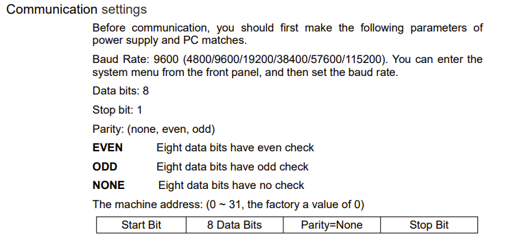
I am trying to control via serial communication from my Arduino an Itech power supply. First I tried to do the same with pyserial in my pc. It worked after defining the device as:
Welcome!
Post an annotated schematic showing exactly how you have wired it, be sure to show all power, ground connections and power source(s). Also post a link to your Itech power supply technical specifications.
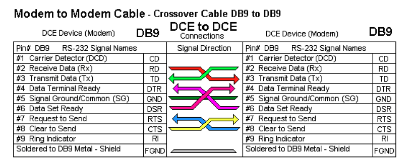
A very common mistake with RS232 is to get the Rx and Tx lines reversed. You may need to swap pins 2 and 3 between the RS232 adapter and the RS232 cable to the Itech power supply.
Depends on the cable, some swap the Rx and Tx pins, some are wired straight through.
For equipment designed to be connected to a PC, the only thing you can reasonably assume is that the cable is wired to work with the standard serial port of a PC. The RS232 adapter for the Arduino may not have the same pinout for Rx and Tx as a PC port, depends on the adapter you have.
Hi @all:
I built the rts-cts protocol and created what I thought was a correct code. Every time I plugged in the channel assigned to cts, the handshake protocol worked wrongly and all signals were not as accurate as without that pin plugged. I swapped pins in the Arduino card and in the adapter (Artekit AK-3232 and AK-3232L | Artekit Labs Tutorials). The problem only depends on the pin associated to the cts channel. The code is this:
#include <SoftwareSerial.h>

// SoftwareSerial on pins 10 (RX), 11 (TX)
#define RS232_RX 10
#define RS232_TX 11
// RTS/CTS pins
#define RTS_PIN 5  // Arduino says it is ready to send
#define CTS_PIN 6  // Arduino checks if it is allowed to send

SoftwareSerial rs232Serial(RS232_RX, RS232_TX);

String inputCommand = "";

void setup() {
  // Set up serial interfaces
  Serial.begin(9600);        // Serial Monitor
  rs232Serial.begin(9600);   // RS232 communication

  // Set pin modes
  pinMode(RTS_PIN, OUTPUT);
  pinMode(CTS_PIN, INPUT);

  // Initially not ready to send
  digitalWrite(RTS_PIN, LOW);

  Serial.println("Type a command and press Enter. Response will be shown if received.");
}

void loop() {
  // ===== Read from Serial Monitor and send to RS-232 =====
  if (Serial.available()) {
    char c = Serial.read();

    // Collect characters into a command
    if (c == '\n' || c == '\r') {
      if (inputCommand.length() > 0) {
        // Signal we want to send
        digitalWrite(RTS_PIN, HIGH);
        delayMicroseconds(100);  // Give time for CTS to respond

        // Wait for CTS HIGH with timeout
        unsigned long timeout = millis() + 1000;  // 1 second
        while (digitalRead(CTS_PIN) != HIGH && millis() < timeout)
          ;

        if (digitalRead(CTS_PIN) == HIGH) {
          rs232Serial.println(inputCommand);  // Send the command
          rs232Serial.flush();                // Wait for transmit to complete
          Serial.print(">> Sent: ");
          Serial.println(inputCommand);
        } else {
          Serial.println("CTS timeout - RS232 device not ready.");
        }

        digitalWrite(RTS_PIN, LOW);  // Done sending
        inputCommand = "";           // Clear input
      }
    } else {
      inputCommand += c;  // Append character
    }
  }

  // ===== Read from RS-232 and show on Serial Monitor =====
  if (rs232Serial.available()) {
    String response = rs232Serial.readStringUntil('\n');
    Serial.print("<< Received: ");
    Serial.println(response);
  }
}
Trying to find a solution, I did the following code, which keeps the rts channel on for a while in case one wants to read from the device:
#include <SoftwareSerial.h>

// SoftwareSerial pins
#define RS232_RX 10
#define RS232_TX 11

// RTS pin
#define RTS_PIN 2

SoftwareSerial rs232Serial(RS232_RX, RS232_TX);

String inputCommand = "";

void setup() {
  Serial.begin(9600);
  rs232Serial.begin(9600);

  pinMode(RTS_PIN, OUTPUT);
  digitalWrite(RTS_PIN, LOW);

  Serial.println("Type any command and press Enter. Waiting for response...");
}

void loop() {
  // === Collect input from Serial Monitor ===
  while (Serial.available()) {
    char c = Serial.read();
    if (c == '\n' || c == '\r') {
      if (inputCommand.length() > 0) {
        digitalWrite(RTS_PIN, HIGH);
        delayMicroseconds(1000);
        rs232Serial.println(inputCommand);
        Serial.print(">> Sent: ");
        Serial.println(inputCommand);

        unsigned long startTime = millis();
        while (millis() - startTime < 2000) {
          if (rs232Serial.available()) {
            String response = rs232Serial.readStringUntil('\n');
            Serial.print("<< Received: ");
            Serial.println(response);
            break;
          }
        }

        digitalWrite(RTS_PIN, LOW);
        inputCommand = "";
      }
    } else {
      inputCommand += c;
    }
  }
}
I can now type for example *IDN?, but no other command to for example swap the channel value or see the channel value. Also i do not get a response after typing *IDN?.
I will keep trying from time to time. Thx for your support!!
Somehow, if I connect the device to python, disconnect it and then connect it to arduino, commands work! Now I am missing the messages generated by the device to get them in my serial terminal. If I manage, I will post it for other people.
You seem to not know that ALL the pins require RS-232 protocol, including the RTS/CTS connections. Are you using a separate adapter for the RTS/CTS connections?