In this Spanish video: YouTube video (at 0:56),
they say both modules are equivalent, but one uses software control and the other uses hardware control.
So I'm confused about how I should connect them and what code I should use.
Start by telling/showing us how you think they should go together. What do you want the Arduino to do? That will tell you what code to make/use for your project.
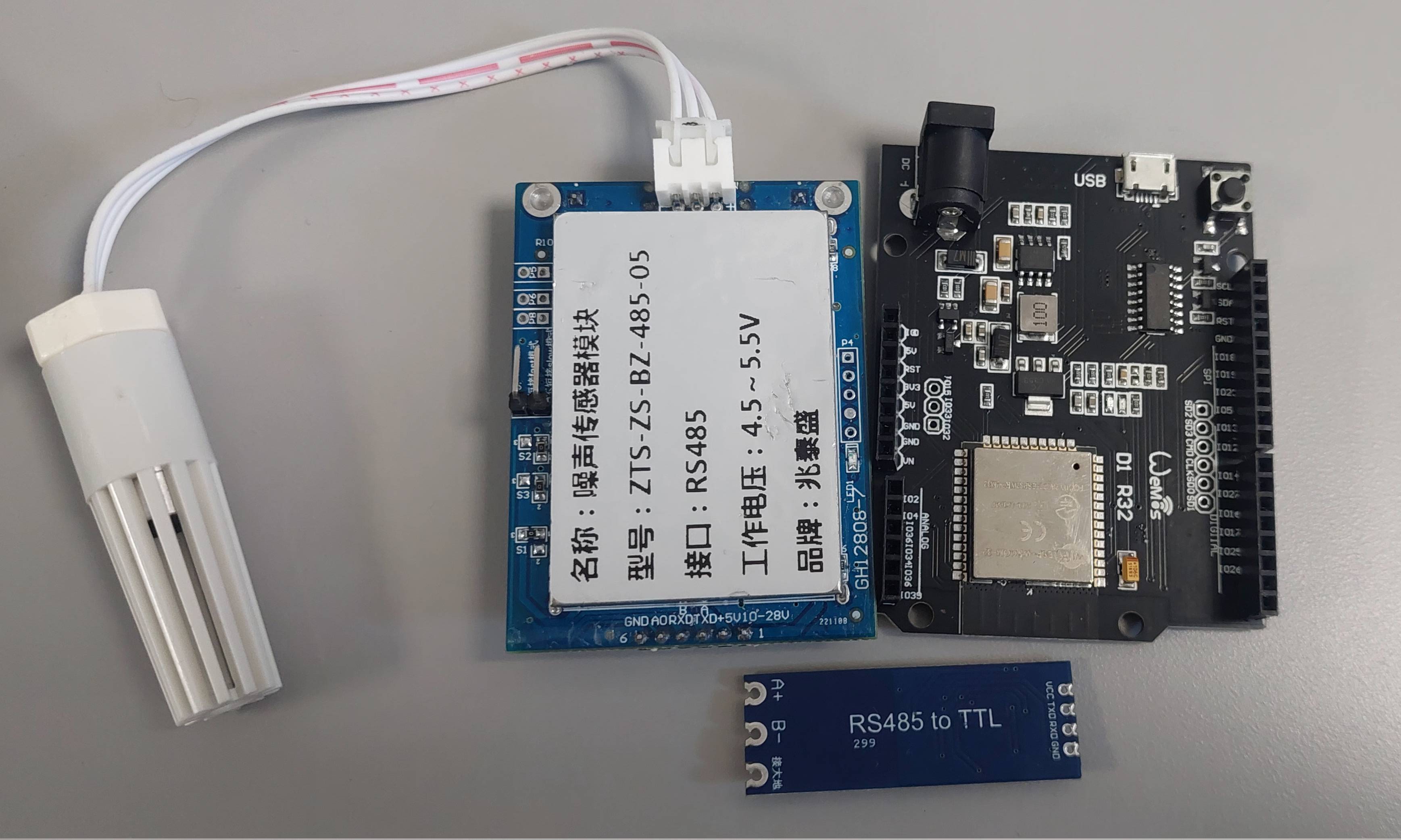
As far as I understand, the noise sensor should be connected to the TTL to RS485 module, and then that module should connect to the ESP32.
The goal is to read the noise level (in dB) from the sensor using the ESP32.
Your link to AE description gives 3 options for communications. Uart TTL, RS485 and analog.
Is there a reason for you to use RS485? If distance between sensor and Esp is short, it doesn't make much sense.
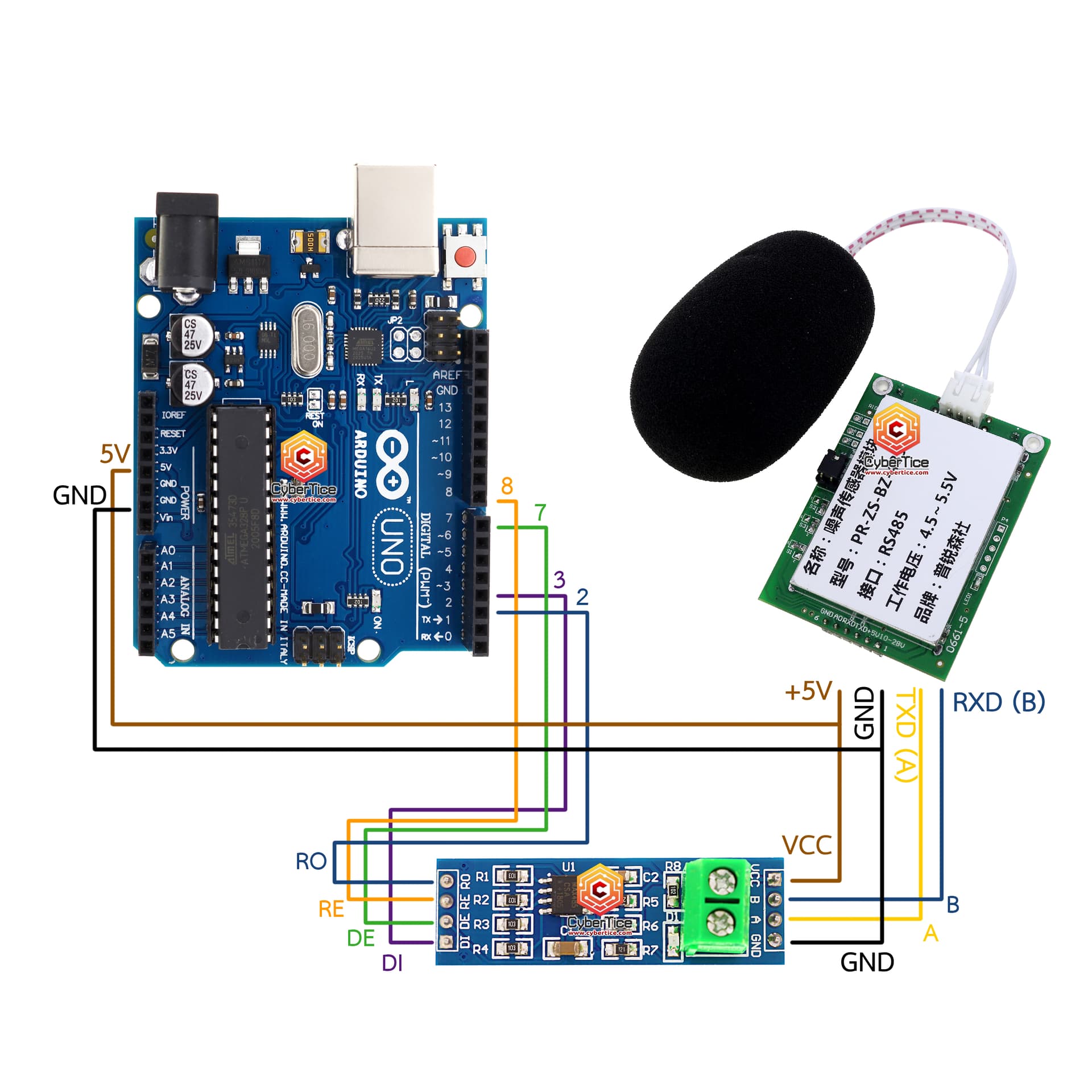
Sensor uses modbus rtu protocol for serial communication, so I suggest you to try this library available on Arduino IDE library manager: https://github.com/4-20ma/ModbusMaster:
From what I've read, the Modbus RTU protocol uses a MAX485 (just like in the Cybertice project I mentioned). So, what would be the difference in this case?
My main problem right now is that I don’t know how to wire the modules correctly.
Is it necessary to use a MAX485 chip specifically, or can the TTL to RS485 module I already have work too?
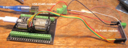
Initially I would recommend connecting the Wemos R1 ESP32 based dev module to a PC via RS485
this would enable you to get some experience with programming the ESP32 and testing the TTL-RS485 module
you would require a USB-RS485 module to interface the PC to RS485 - I use a FTDI usb-rs485-we-1800-bt (similar modules are available of EBAY in the UK for about £10 - see photo)
to connect the TTL-RS485 module to the Wemos D1 R32 have a look at
// ESP32 Serial1 to RS485 bus
//
// see https://microcontrollerslab.com/rs485-serial-communication-arduino-tutorial/

#define RS485Serial Serial1  // hardware serial port on ESP32

// RS485 VCC ESP32 to to 3.3V
#define RXD2 16  //  ESP32 Serial1 Receive  pin 16 to RS485 RO  (Receiver Output) /RXD
#define TXD2 17  //  ESP32 Serial1 Transmit pin 17 to RS485 DI  (Driver Input) /TXD

// RS485 DE (Driver Enable set HIGH to enable)  and RE (Receiver Enable set LOW to enable) to ESP32 pins 18 and 19
#define DE 18  //RS485 Direction control pin
#define RE 19  //RS485 Direction control pin

#define RS485Transmit HIGH
#define RS485Receive LOW

void setup() {
  Serial.begin(115200);
  delay(1000);
  Serial.println("ESP32 connect to RS485 bus - enter/receive text");
  pinMode(DE, OUTPUT);
  pinMode(RE, OUTPUT);
  digitalWrite(DE, RS485Receive);                     // Disable RS485 Transmit
  digitalWrite(RE, RS485Receive);                     // Disable RS485 Transmit
  RS485Serial.begin(115200, SERIAL_8N1, RXD2, TXD2);  // set the RS485 data rate
}

// loop sending data to RS485 and receiving data
void loop() {
  if (Serial.available()) {            // Arduino Serial data avaliable?
    digitalWrite(DE, RS485Transmit);   // Enable RS485 Transmit
    digitalWrite(RE, RS485Transmit);   // Enable RS485 Transmit
    RS485Serial.write(Serial.read());  // Send byte to Remote Arduino
    RS485Serial.flush();               // wait for byte to be transmitted
    digitalWrite(DE, RS485Receive);    // Disable RS485 Transmit
    digitalWrite(RE, RS485Receive);    // Disable RS485 Transmit
  }

  if (RS485Serial.available())         // RS485 serial data available?
    Serial.write(RS485Serial.read());  // read character and display it
}
serial output when ESP32 with TTL-RS485 module connected to a PC via a USB-RS485
ESP32 to PC via RS485

PC teraterm (local echo on)
test1 from ESP32
test2 1234567890
test3 abcdefghijk
test1 from pc
test 2 from pc 1234567890
test3 from pc abcdef
test4 from ESP32 98765432

ESP32
test1 from pc
test 2 from pc 1234567890
test3 from pc abcdef
even when you get to the stage of connecting the RS485 noise sensor you can leave the USB-RS485 module connected to the bus - it is useful looking a data flow and debugging