Hey raidersnake,
Thanks for the tips. My project is essentially just logging 4 0-3.3V inputs to an SD card at up to 2KHz. It's part of a bigger sensor that my group is working on. I've been poking and prodding at it, and managed to get it to run with your advice. However, I don't get either of the results1... variables to ever go true. I'm not sure how terrible of an issue this is, lol.
I think I may have some misunderstandings about this program. If you could answer some of my questions I might be able to understand this better:
- What exactly is the difference between the two result arrays? I've been able to get readings from all 4 pins in just
adcResults0.adcResults1doesn't get updated (see 7). - When setting up the Channel 2 descriptor for DMA Sequencing, why is the
srcaddrset to the end of theinputCtrl0array? I would think it should be set to the start. - When setting up the Channel 3 and 4 descriptors, is there a reason why
dstaddris not just set to&adcResults*[1024]? - When setting up the Channel 0 and 1 descriptors, why is
dstaddrset to the end of theadcResultsarrays? - Could you explain what the
NVIC_SetPriority()andNVIC_EnableIRQ()calls do? - For the
adcResults*arrays, is "part 0" the first half and "part 1" the second half? I assume the DMAC is operating on one half of each at any one time, leaving the other half safe to use. - Could you explain how the two Handler() functions at the end are used? I don't see them called anywhere, but throwing a print statement in either shows that, while the Chanenl 3 handler is called continuously, the Channel 4 handler is only called once (that I can tell) at the very beginning of the program. Also,
results1Part0Readyandresults1Part1Readydon't go true besides near the start of the program. I assume these two issues are related. Any ideas for this one? - Less of a code question, but I've noticed that when holding a single pin to 3.3V, if the other pins are floating/not connected, the other three pins seem to be influenced by the pin at 3.3V:
Do you think this is simply because three of the pins are floating? Or would you say that, if I connected the other pins to their own inputs, every pin would influence the reading of every other pin?
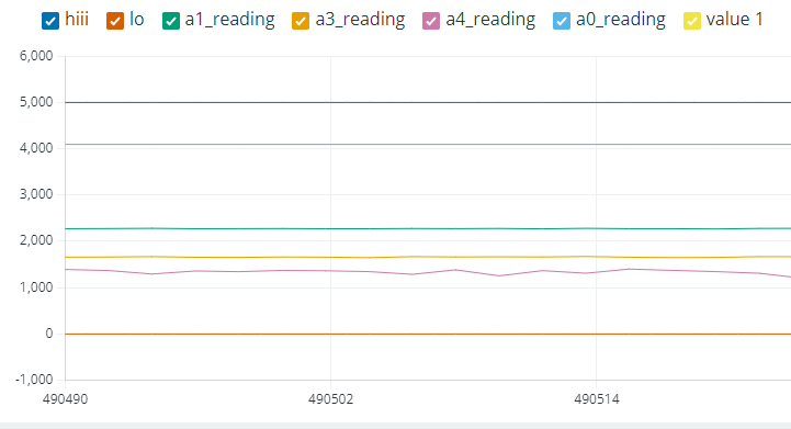
For reference, here is my code. I've made a couple edits here and there, but the meat of it is the same. It's set up to work with the Arduino IDE's serial plotter.
#include "FreeStack.h"
#include "SdFat.h"
#include "sdios.h"
#define error(s) sd.errorHalt(&Serial, F(s))
const uint8_t SD_CS_PIN = 10;
#define SPI_CLOCK SD_SCK_MHZ(50)
#define SD_CONFIG SdSpiConfig(SD_CS_PIN, DEDICATED_SPI, SPI_CLOCK)
#define NUM_SAMPLES_2 2048 // two times the number of samples per pin. i.e. each pin will get half of this number in samples
SdFs sd;
FsFile file;
#define DEBUG_R0_P0 1
#define DEBUG_R0_P1 0
#define DEBUG_R1_P0 1
#define DEBUG_R1_P1 1
#define DEBUG_SD_BEGIN 1
volatile boolean results0Part0Ready = false;
volatile boolean results0Part1Ready = false;
volatile boolean results1Part0Ready = false;
volatile boolean results1Part1Ready = false;
uint16_t adcResults0[NUM_SAMPLES_2]; // ADC results array 0
uint16_t adcResults1[NUM_SAMPLES_2]; // ADC results array 1
// ADC0 INPUTCTRL register MUXPOS settings
uint32_t inputCtrl0[] = { ADC_INPUTCTRL_MUXPOS_AIN0, // AIN0 = A0
ADC_INPUTCTRL_MUXPOS_AIN5, // AIN5 = A1
ADC_INPUTCTRL_MUXPOS_AIN3, // AIN3 = A3
ADC_INPUTCTRL_MUXPOS_AIN4 }; // AIN4 = A4
typedef struct // DMAC descriptor structure
{
uint16_t btctrl;
uint16_t btcnt;
uint32_t srcaddr;
uint32_t dstaddr;
uint32_t descaddr;
} dmacdescriptor ;
volatile dmacdescriptor (*wrb)[DMAC_CH_NUM] __attribute__ ((aligned (16))); // Write-back DMAC descriptors (changed to array pointer)
dmacdescriptor (*descriptor_section)[DMAC_CH_NUM] __attribute__ ((aligned (16))); // DMAC channel descriptors (changed to array pointer)
dmacdescriptor descriptor __attribute__ ((aligned (16))); // Place holder descriptor
dmacdescriptor linked_descriptor[2] __attribute__ ((aligned (16)));
void setup() {
Serial.begin(115200); // Start the native USB port
while(!Serial); // Wait for the console to open
#if DEBUG_SD_BEGIN
// Initialize SD card before setting up DMA
if (!sd.begin(SD_CONFIG)) {
Serial.println("SD initialization failed!");
while (1); // Halt if SD card initialization fails
} else {
Serial.println("SD initialization succeeded!");
}
#endif
pinMode(10, OUTPUT); // Initialise the output on D10 for debug purposes
PORT->Group[PORTB].DIRSET.reg = PORT_PB23; // Initialise the output on D11 for debug purposes TODO: make it autoselect based on board
descriptor_section = reinterpret_cast<dmacdescriptor(*)[DMAC_CH_NUM]>(DMAC->BASEADDR.reg); //point array pointer to BASEADDR defined by SD.begin
wrb = reinterpret_cast<dmacdescriptor(*)[DMAC_CH_NUM]>(DMAC->WRBADDR.reg); //point array pointer to WRBADDR defined by SD.begin
DMAC->CTRL.reg = DMAC_CTRL_DMAENABLE | DMAC_CTRL_LVLEN(0xf); // Enable the DMAC peripheral and all priority levels
// ADC0 DMA Sequencing setup
DMAC->Channel[2].CHPRILVL.reg = DMAC_CHPRILVL_PRILVL_LVL3; // Set DMAC channel 2 to priority level 3 (highest)
DMAC->Channel[2].CHCTRLA.reg = DMAC_CHCTRLA_TRIGSRC(ADC0_DMAC_ID_SEQ) | // Set DMAC to trigger on ADC0 DMAC sequence
DMAC_CHCTRLA_BURSTLEN_SINGLE | // One beat per burst
DMAC_CHCTRLA_TRIGACT_BURST; // DMAC burst transfer
DMAC->Channel[2].CHINTENSET.reg = DMAC_CHINTENSET_SUSP; // Activate the suspend (SUSP) interrupt on DMAC channel 2
descriptor.descaddr = (uint32_t)&(*descriptor_section)[2]; // Set up a circular descriptor
descriptor.srcaddr = (uint32_t)inputCtrl0 + sizeof(uint32_t) * 4; // Configure the DMAC to set the (???)
descriptor.dstaddr = (uint32_t)&ADC0->DSEQDATA.reg; // Write the INPUT CTRL
descriptor.btcnt = 4;//TODO TODO TODO TODO TODO // Beat count is 2 (???) (code originally had it at 4) TODO TODO TODO TODO TODO
descriptor.btctrl = DMAC_BTCTRL_BEATSIZE_WORD | // Beat size is WORD (32-bits)
DMAC_BTCTRL_SRCINC | // Increment the source address
DMAC_BTCTRL_STEPSEL_SRC | // Indicates that the source address is using these step settings
DMAC_BTCTRL_STEPSIZE_X1 | // The Step size is set to 1x beats
DMAC_BTCTRL_VALID; // Descriptor is valid
memcpy(&(*descriptor_section)[2], &descriptor, sizeof(descriptor)); // Copy the descriptor to the descriptor section
// ADC0
DMAC->Channel[3].CHPRILVL.reg = DMAC_CHPRILVL_PRILVL_LVL3; // Set DMAC channel 3 to priority level 3 (highest)
DMAC->Channel[3].CHCTRLA.reg = DMAC_CHCTRLA_TRIGSRC(ADC0_DMAC_ID_RESRDY) | // Set DMAC to trigger when ADC0 result is ready
DMAC_CHCTRLA_TRIGACT_BURST; // DMAC burst transfer
descriptor.descaddr = (uint32_t)&(*descriptor_section)[0]; // Set up a circular descriptor
descriptor.srcaddr = (uint32_t)&ADC0->RESULT.reg; // Take the result from the ADC0 RESULT register
descriptor.dstaddr = (uint32_t)adcResults0 + sizeof(uint16_t) * (NUM_SAMPLES_2/2); // Place it in the middle of adcResults0 array
descriptor.btcnt = (NUM_SAMPLES_2/2); // Beat count
descriptor.btctrl = DMAC_BTCTRL_BEATSIZE_HWORD | // Beat size is HWORD (16-bits)
DMAC_BTCTRL_DSTINC | // Increment the destination address
DMAC_BTCTRL_VALID | // Descriptor is valid
DMAC_BTCTRL_BLOCKACT_SUSPEND; // Suspend DMAC channel 3 after block transfer
memcpy(&(*descriptor_section)[3], &descriptor, sizeof(descriptor)); // Copy the descriptor to the descriptor section
descriptor.descaddr = (uint32_t)&(*descriptor_section)[3]; // Set up a circular descriptor
descriptor.srcaddr = (uint32_t)&ADC0->RESULT.reg; // Take the result from the ADC0 RESULT register
descriptor.dstaddr = (uint32_t)&adcResults0[NUM_SAMPLES_2/2] + sizeof(uint16_t) * (NUM_SAMPLES_2/2); // Place it in the adcResults0 array
descriptor.btcnt = (NUM_SAMPLES_2/2); // Beat count
descriptor.btctrl = DMAC_BTCTRL_BEATSIZE_HWORD | // Beat size is HWORD (16-bits)
DMAC_BTCTRL_DSTINC | // Increment the destination address
DMAC_BTCTRL_VALID | // Descriptor is valid
DMAC_BTCTRL_BLOCKACT_SUSPEND; // Suspend DMAC channel 0 after block transfer
memcpy(&(*descriptor_section)[0], &descriptor, sizeof(descriptor)); // Copy the descriptor to the descriptor section
NVIC_SetPriority(DMAC_3_IRQn, 0); // Set the Nested Vector Interrupt Controller (NVIC) priority for DMAC Channel 3
NVIC_EnableIRQ(DMAC_3_IRQn); // Connect DMAC Channel 0 to Nested Vector Interrupt Controller (NVIC)
DMAC->Channel[3].CHINTENSET.reg = DMAC_CHINTENSET_SUSP; // Activate the suspend (SUSP) interrupt on DMAC channel 3
// ADC1
DMAC->Channel[4].CHPRILVL.reg = DMAC_CHPRILVL_PRILVL_LVL3; // Set DMAC channel 4 to priority level 3 (highest)
DMAC->Channel[4].CHCTRLA.reg = DMAC_CHCTRLA_TRIGSRC(ADC1_DMAC_ID_RESRDY) | // Set DMAC to trigger when ADC0 result is ready
DMAC_CHCTRLA_TRIGACT_BURST; // DMAC burst transfer
descriptor.descaddr = (uint32_t)&(*descriptor_section)[1]; // Set up a circular descriptor
descriptor.srcaddr = (uint32_t)&ADC1->RESULT.reg; // Take the result from the ADC0 RESULT register
descriptor.dstaddr = (uint32_t)adcResults1 + sizeof(uint16_t) * (NUM_SAMPLES_2/2); // Place it in the adcResults1 array
descriptor.btcnt = (NUM_SAMPLES_2/2); // Beat count
descriptor.btctrl = DMAC_BTCTRL_BEATSIZE_HWORD | // Beat size is HWORD (16-bits)
DMAC_BTCTRL_DSTINC | // Increment the destination address
DMAC_BTCTRL_VALID | // Descriptor is valid
DMAC_BTCTRL_BLOCKACT_SUSPEND; // Suspend DMAC channel 4 after block transfer
memcpy(&(*descriptor_section)[4], &descriptor, sizeof(descriptor)); // Copy the descriptor to the descriptor section
descriptor.descaddr = (uint32_t)&(*descriptor_section)[4]; // Set up a circular descriptor
descriptor.srcaddr = (uint32_t)&ADC1->RESULT.reg; // Take the result from the ADC0 RESULT register
descriptor.dstaddr = (uint32_t)&adcResults1[1024] + sizeof(uint16_t) * (NUM_SAMPLES_2/2); // Place it in the adcResults1 array
descriptor.btcnt = (NUM_SAMPLES_2/2); // Beat count
descriptor.btctrl = DMAC_BTCTRL_BEATSIZE_HWORD | // Beat size is HWORD (16-bits)
DMAC_BTCTRL_DSTINC | // Increment the destination address
DMAC_BTCTRL_VALID | // Descriptor is valid
DMAC_BTCTRL_BLOCKACT_SUSPEND; // Suspend DMAC channel 4 after block transfer
memcpy(&linked_descriptor[1], &descriptor, sizeof(descriptor)); // Copy the descriptor to the descriptor section
NVIC_SetPriority(DMAC_4_IRQn, 0); // Set the Nested Vector Interrupt Controller (NVIC) priority for DMAC Channel 4
NVIC_EnableIRQ(DMAC_4_IRQn); // Connect DMAC Channel 0 to Nested Vector Interrupt Controller (NVIC)
DMAC->Channel[4].CHINTENSET.reg = DMAC_CHINTENSET_SUSP; // Activate the suspend (SUSP) interrupt on DMAC channel 0
// ADC Register Settings
ADC1->INPUTCTRL.bit.MUXPOS = ADC_INPUTCTRL_MUXPOS_AIN3_Val; // Set the analog input to A2
while(ADC1->SYNCBUSY.bit.INPUTCTRL); // Wait for synchronization
ADC1->SAMPCTRL.bit.SAMPLEN = 0x00; // Extend sampling time by SAMPCTRL ADC cycles (12 + 1 + 2)/750kHz = 20us = 50kHz
while(ADC1->SYNCBUSY.bit.SAMPCTRL); // Wait for synchronization
ADC1->DSEQCTRL.reg = ADC_DSEQCTRL_AUTOSTART | // Auto start a DMAC conversion upon ADC0 DMAC sequence completion
ADC_DSEQCTRL_INPUTCTRL; // Change the ADC0 INPUTCTRL register on DMAC sequence
ADC1->CTRLB.reg = ADC_CTRLB_RESSEL_12BIT; // Set ADC resolution to 12 bits
while(ADC1->SYNCBUSY.bit.CTRLB); // Wait for synchronization
ADC1->CTRLA.bit.SLAVEEN = 1; // Set ADC1 to slave, ADC0 to master, both share CTRLA register
ADC0->INPUTCTRL.bit.MUXPOS = ADC_INPUTCTRL_MUXPOS_AIN0_Val; // Set the analog input to A0
while(ADC0->SYNCBUSY.bit.INPUTCTRL); // Wait for synchronization
ADC0->SAMPCTRL.bit.SAMPLEN = 0x00; // Extend sampling time by SAMPCTRL ADC cycles (12 + 1 + 2)/750kHz = 20us = 50kHz
while(ADC0->SYNCBUSY.bit.SAMPCTRL); // Wait for synchronization
ADC0->DSEQCTRL.reg = ADC_DSEQCTRL_AUTOSTART | // Auto start a DMAC conversion upon ADC0 DMAC sequence completion
ADC_DSEQCTRL_INPUTCTRL; // Change the ADC0 INPUTCTRL register on DMAC sequence
ADC0->CTRLB.reg = ADC_CTRLB_RESSEL_12BIT; // Set ADC resolution to 12 bits
while(ADC0->SYNCBUSY.bit.CTRLB); // Wait for synchronization
ADC0->CTRLA.reg = ADC_CTRLA_PRESCALER_DIV4; // Divide Clock ADC GCLK by 4 (48MHz/64 = 750kHz) (12 + 1)/750kHz = 17.3us sample time
ADC0->CTRLA.bit.ENABLE = 1; // Enable the ADC
while(ADC0->SYNCBUSY.bit.ENABLE); // Wait for synchronization
ADC0->SWTRIG.bit.START = 1; // Initiate a software trigger to start an ADC conversion
while(ADC0->SYNCBUSY.bit.SWTRIG); // Wait for synchronization
DMAC->Channel[2].CHCTRLA.bit.ENABLE = 1; // Enable DMAC channel 2
DMAC->Channel[3].CHCTRLA.bit.ENABLE = 1; // Enable DMAC channel 3
DMAC->Channel[4].CHCTRLA.bit.ENABLE = 1; // Enable DMAC channel 4
delay(1); // Wait a millisecond
}
void loop()
{
// Serial.println("Loop Start");
Serial.print("hiii:");
Serial.print(5000);
Serial.print(",");
Serial.print("lo:");
Serial.print(0);
Serial.print(",");
// debugPrintStatus();
if (results0Part0Ready) // Display the results in results0 array
{
#if DEBUG_R0_P0
Serial.print("a1_reading:");
Serial.print(adcResults0[0]);
Serial.print(", ");
Serial.print("a3_reading:");
Serial.print(adcResults0[1]);
Serial.print(", ");
Serial.print("a4_reading:");
Serial.print(adcResults0[2]);
Serial.print(", ");
Serial.print("a0_reading:");
Serial.print(adcResults0[3]);
#endif
Serial.println();
results0Part0Ready = false; // Clear the results0 ready flag
}
if (results0Part1Ready) // Display the results in results1 array
{
#if DEBUG_R0_P1
Serial.print("a3_reading:");
Serial.print(adcResults0[1024]);
Serial.print(", ");
Serial.print("a4_reading:");
Serial.print(adcResults0[1025]);
Serial.print(", ");
Serial.print("a0_reading:");
Serial.print(adcResults0[1026]);
Serial.print(", ");
Serial.print("a1_reading:");
Serial.print(adcResults0[1027]);
#endif
Serial.println();
results0Part1Ready = false; // Clear the results1 ready flag
}
if (results1Part0Ready) // Display the results in results0 array
{
#if DEBUG_R1_P0
Serial.print("3_reading:");
Serial.print(ADC1->RESULT.reg);
Serial.print(",");
#endif
Serial.println();
results1Part0Ready = false; // Clear the results0 ready flag
}
if (results1Part1Ready) // Display the results in results1 array
{
#if DEBUG_R1_P1
Serial.print("4_reading:");
Serial.print(ADC1->RESULT.reg);
Serial.print(",");
#endif
Serial.println();
results1Part1Ready = false; // Clear the results1 ready flag
}
}
void DMAC_3_Handler() // Interrupt handler for DMAC channel 3
{
// Serial.println("AAAAAAAAAAAAAAAAAAAAAAAAAAAAAAAAAAAAAAAAAAAAAAAAA");
static uint8_t count0 = 0; // Initialise the count
if (DMAC->Channel[3].CHINTFLAG.bit.SUSP) // Check if DMAC channel 3 has been suspended (SUSP)
{
DMAC->Channel[3].CHCTRLB.reg = DMAC_CHCTRLB_CMD_RESUME; // Restart the DMAC on channel 3
DMAC->Channel[3].CHINTFLAG.bit.SUSP = 1; // Clear the suspend (SUSP)interrupt flag
if (count0) // Test if the count0 is 1
{
results0Part1Ready = true; // Set the results 0 part 1 ready flag
}
else
{
results0Part0Ready = true; // Set the results 0 part 0 ready flag
}
count0 = (count0 + 1) % 2; // Toggle the count0 between 0 and 1
digitalWrite(10, HIGH); // Toggle the output high then low on D10 for debug purposes
delayMicroseconds(3); // Short delay for visualization
digitalWrite(10, LOW);
}
}
void DMAC_4_Handler() // Interrupt handler for DMAC channel 4
{
Serial.println("BBBBBBBBBBBBBBBBBBBBBBBBBBBBBBBBBBBBBBBBBBBBBBB");
static uint8_t count1 = 0; // Initialise the count
if (DMAC->Channel[4].CHINTFLAG.bit.SUSP) // Check if DMAC channel 4 has been suspended (SUSP)
{
DMAC->Channel[4].CHCTRLB.reg = DMAC_CHCTRLB_CMD_RESUME; // Restart the DMAC on channel 4
DMAC->Channel[4].CHINTFLAG.bit.SUSP = 1; // Clear the suspend (SUSP)interrupt flag
if (count1) // Test if the count1 is 1
{
results1Part1Ready = true; // Set the results 1 part 1 ready flag
}
else
{
results1Part0Ready = true; // Set the results 1 part 0 ready flag
}
count1 = (count1 + 1) % 2; // Toggle the count1 between 0 and 1
PORT->Group[PORTB].OUTSET.reg = PORT_PB23; // Toggle D10 HIGH // Toggle the output high then low on D11 for debug purposes
delayMicroseconds(3); // Short delay for visualization
PORT->Group[PORTB].OUTCLR.reg = PORT_PB23; // Toggle D10 LOW
}
}
void debugPrintStatus() {
// Print out DMAC channel status and flags
Serial.println(F("=== DMAC Channel Status ==="));
for (int i = 0; i < 5; i++) {
Serial.print(F("Channel ")); Serial.println(i);
Serial.print(F(" CHCTRLA: ")); Serial.println(DMAC->Channel[i].CHCTRLA.reg, HEX);
Serial.print(F(" CHCTRLB: ")); Serial.println(DMAC->Channel[i].CHCTRLB.reg, HEX);
Serial.print(F(" CHINTFLAG: ")); Serial.println(DMAC->Channel[i].CHINTFLAG.reg, HEX);
Serial.print(F(" CHINTENSET: ")); Serial.println(DMAC->Channel[i].CHINTENSET.reg, HEX);
Serial.print(F(" CHINTENCLR: ")); Serial.println(DMAC->Channel[i].CHINTENCLR.reg, HEX);
// Print descriptor information
Serial.print(F(" Descriptor Address: ")); Serial.println((uint32_t)&(*descriptor_section)[i], HEX);
Serial.print(F(" BTCNT: ")); Serial.println((*descriptor_section)[i].btcnt);
Serial.print(F(" SRCADDR: ")); Serial.println((uint32_t)(*descriptor_section)[i].srcaddr, HEX);
Serial.print(F(" DSTADDR: ")); Serial.println((uint32_t)(*descriptor_section)[i].dstaddr, HEX);
Serial.print(F(" DESCADDR: ")); Serial.println((uint32_t)(*descriptor_section)[i].descaddr, HEX);
}
// Print ADC status
Serial.println(F("=== ADC Status ==="));
Serial.print(F("ADC0 RESULT: ")); Serial.println(ADC0->RESULT.reg, HEX);
Serial.print(F("ADC0 INTFLAG: ")); Serial.println(ADC0->INTFLAG.reg, HEX);
Serial.print(F("ADC0 STATUS: ")); Serial.println(ADC0->STATUS.reg, HEX);
Serial.print(F("ADC1 RESULT: ")); Serial.println(ADC1->RESULT.reg, HEX);
Serial.print(F("ADC1 INTFLAG: ")); Serial.println(ADC1->INTFLAG.reg, HEX);
Serial.print(F("ADC1 STATUS: ")); Serial.println(ADC1->STATUS.reg, HEX);
// Print other important registers
Serial.println(F("=== Other Important Registers ==="));
Serial.print(F("DMAC BASEADDR: ")); Serial.println(DMAC->BASEADDR.reg, HEX);
Serial.print(F("DMAC WRBADDR: ")); Serial.println(DMAC->WRBADDR.reg, HEX);
Serial.print(F("DMAC CTRL: ")); Serial.println(DMAC->CTRL.reg, HEX);
}
Sorry for the wall of text! Any help would be greatly appreciated 