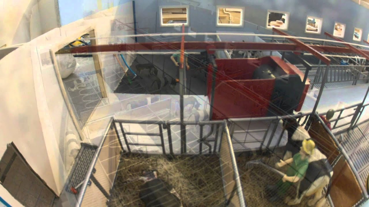
Scale model of automatic feeding robot with stepper. Need help with home pos.

Hi,

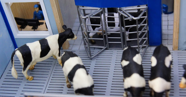
I have been working on this project the last four years, and things are really starting to come together. To start off this question, I will give you some background information to better understand the project. It is a scale model of a fully automated barn for 28 milking cows, and also som calfes, heifers and bulls. The barn has a milking robot (Voluntary milking system) and automatic feeding (FeedRobot). Everything is in 1/32nd scale and I have made everything from scratch, apart from the animals and figures. Some of the parts are 3D-printed, while the rest is hand made from wood, plastic, brass and some other materials as well. The size of the barn is 1250 x 600 mm.

If you want to see any pictures and a couple of videos of the barn you can visit this link with a Google Photos album. These pictures are taken by Steffan Stanes, my neighbor.

Now, to come closer to my issue, or what I want help for. The FeedRobot is moving with the help of a stepper motor controlled by an Arduino Uno R3 with an Adafruit Motor/Stepper/Servo shield V2. I have after lots of trials and fails got this to work almost just as I want. The only issue I have is that I want to make a endstop switch or something similar that makes the robot start in the same position every time.

The program consists of four parts. In all the parts the robot starts with moving forward to the filling position where it moves back and forth a couple of times. After this it moves to the beginning of the section it will feed. From here it varies from the different parts. First it "feeds" (just passes, so it looks like it feeds) the milking cows, which is a long pass. It goes back and forth here two times.
After this it goes back to parking position before it starts next part with "filling up". It then moves to the fourth stall (if that is a correct name) where it passes three times, the same way as with the milking cows. After this it also feeds the cows in the third stall before it goes back to parking position. It then repeats the process of filling and feeding the milking cows. Then it goes back to parking, then filling and feeding the second and first stall. This loop of these four parts goes on and on and takes about 15-20 minutes to complete one loop.

In this video you see how the robot moved in april this year. There are some small changes now, but it is quite similar, and hopefully it makes it easier to understand what I wrote above. The video also contains a time-lapse of the whole loop (all four parts, but without the filling).

Hope this was understandable so far. To make it clearer with this information; I am thinking of an endstop switch or something similar that makes it park at the same position everytime. When the robot goes for about half an hour it has come quite a few millimeters out of position. This has one time leaded to a collision with the endwall. If I can make it park at exactly the same place, it can start from this position everytime, and I don't have to worry about it getting out of position.

I don't know how to do this, but could it be a possibility to program it to go past the endswitch, and make this switch stop it? Hope you guys can help me here. Below is the code I have now. Don't mind if the number of steps is uneven each way, or something, as these numbers are in constant change to make it perfect. All the comments were in Norwegian, as I am from Norway, but I have translated most of them, so it is easier to understand the code. I have removed the third and fourth part, as they are almost exactly like part one and two.

#include <Wire.h>
#include <Adafruit_MotorShield.h>
#include "utility/Adafruit_PWMServoDriver.h"

Adafruit_MotorShield AFMS = Adafruit_MotorShield();
Adafruit_StepperMotor *FeedRobot = AFMS.getStepper(200,2);
#define Kuborste 9
int led = 13;

void setup() {
Serial.begin(9600);
Serial.println("FeedRobot");
AFMS.begin();
FeedRobot->setSpeed(150); //hastighet - speed
pinMode (led, OUTPUT);
pinMode (Kuborste, OUTPUT);

}

void loop() {
  //Starte kuborste med boost - start cow brush with a "boost"
  analogWrite (Kuborste,200);
  delay(250);
  analogWrite (Kuborste,90); //kuborste i vanlig hastighet - Cow brush in normal speed

//Melkekyr 1. gang - milking cows first time
  digitalWrite(led, HIGH); // Varsel om at roboten begynner å kjøre - warning light to indicate the robot will start
  delay(5000);
  FeedRobot->step(230, FORWARD, MICROSTEP); //Fylling - Filling up
  delay(8000);
  FeedRobot->step(30, BACKWARD, MICROSTEP); //Fylling - Filling up
  delay(8000);
  FeedRobot->step(30, FORWARD, MICROSTEP); //Fylling - Filling up
  delay(8000);
  FeedRobot->step(30, BACKWARD, MICROSTEP); //Fylling - Filling up
  delay(8000);
  FeedRobot->step(30, FORWARD, MICROSTEP); //Fylling - Filling up
  delay(8000);
  digitalWrite(led, LOW); //Varsellampe slukkes - warning light turns off
  FeedRobot->step(410, FORWARD, MICROSTEP); //Fram til begynnelse av foring - To beginning of first feeding area
  delay(3000);
  FeedRobot->step(1030, FORWARD, MICROSTEP); //Foring for melkekyr - Feed the milking cows
  delay(3000);
  FeedRobot->step(1030, BACKWARD, MICROSTEP); //Foring for melkekyr - Feed the milking cows
  delay(3000);
  FeedRobot->step(1030, FORWARD, MICROSTEP); //Foring for melkekyr - Feed the milking cows
  delay(3000);
  FeedRobot->step(1030, BACKWARD, MICROSTEP); //Foring for melkekyr - Feed the milking cows
  delay(3000);
  FeedRobot->step(340, BACKWARD, MICROSTEP); //Tilbake til hjemposisjon, før varsel - back to home position before warning light
  digitalWrite(led, HIGH); //Varsel om at roboten snart kommer - warning that the robot is coming
  delay(3000);
  FeedRobot->step(300, BACKWARD, MICROSTEP); //Tilbake til hjemposisjon - back to home position
  digitalWrite(led, LOW); //Varsellampe slukkes - warning light turns off
  delay(7000);
  
  analogWrite(Kuborste,200); //Kubørste "boost" - cow brush boost in case it has stopped
  delay(250);
  analogWrite(Kuborste,90);  //kubørste - cow brush normal speed
  
  //Binge 4 og 3 - stall 4 and 3
  digitalWrite(led, HIGH); //Varsel om at roboten begynner å kjøre - warning light to indicate the robot will start
  delay(5000);
  FeedRobot->step(230, FORWARD, MICROSTEP); //Fylling - Filling up
  delay(8000);
  FeedRobot->step(30, BACKWARD, MICROSTEP); //Fylling - Filling up
  delay(8000);
  FeedRobot->step(30, FORWARD, MICROSTEP); //Fylling - Filling up
  delay(8000);
  FeedRobot->step(30, BACKWARD, MICROSTEP); //Fylling - Filling up
  delay(8000);
  FeedRobot->step(30, FORWARD, MICROSTEP); //Fylling - Filling up
  delay(8000);
  digitalWrite(led, LOW); //Varsellampe slukkes - warning light turns off
  FeedRobot->step(1305, FORWARD, MICROSTEP); //Fram til fjerde binge - To beginning of fourth stall
  delay(3000);
  FeedRobot->step(145, FORWARD, MICROSTEP); //Fjerde binge fram - feeding forward fourth stall
  delay(2000);
  FeedRobot->step(145, BACKWARD, MICROSTEP); //Fjerde binge bak - feeding backward fourth stall
  delay(2000);
  FeedRobot->step(145, FORWARD, MICROSTEP); //Fjerde binge fram - feeding forward fourth stall
  delay(2000);
  FeedRobot->step(145, BACKWARD, MICROSTEP); //Fjerde binge bak - feeding backward fourth stall
  delay(2000);
  FeedRobot->step(145, FORWARD, MICROSTEP); //Fjerde binge fram - feeding forward fourth stall
  delay(2000);
  FeedRobot->step(145, BACKWARD, MICROSTEP); //Fjerde binge bak - feeding backward fourth stall
  delay(2000);
  FeedRobot->step(295, BACKWARD, MICROSTEP); //Tilbake til tredje binge - going back to beginning of third stall
  delay(3000);
  FeedRobot->step(175, FORWARD, MICROSTEP); //Tredje binge fram - feeding forward third stall
  delay(2000);
  FeedRobot->step(175, BACKWARD, MICROSTEP); //Tredje binge bak - feeding backward third stall
  delay(2000);
  FeedRobot->step(175, FORWARD, MICROSTEP); //Tredje binge fram - feeding forward third stall
  delay(2000);
  FeedRobot->step(175, BACKWARD, MICROSTEP); //Tredje binge bak - feeding backward third stall
  delay(2000);
  FeedRobot->step(175, FORWARD, MICROSTEP); //Tredje binge fram - feeding forward third stall
  delay(2000);
  FeedRobot->step(175, BACKWARD, MICROSTEP); //Tredje binge bak - feeding backward third stall
  delay(2000);
  FeedRobot->step(930, BACKWARD, MICROSTEP); //Tilbake til hjemposisjon, før varsellampe - back to home position, before warning light
  digitalWrite(led, HIGH); //Varsel om at roboten snart kommer - warning light indicating the robot is coming
  delay(3000);
  FeedRobot->step(300, BACKWARD, MICROSTEP); //Tilbake til hjemposisjon - back to home position
  digitalWrite(led, LOW); //Varsellampe slukkes - warning light turns off
  delay(7000);
  
  analogWrite(Kuborste,200);
  delay(250);
  analogWrite(Kuborste,90);  //kubørste
  

}
The usual way to establish the HOME or ZERO position is with some code in a loop that functions like this pseudo code

limitSwitchState = digitalRead(limitSwitchPin);
while (limitSwitchState == HIGH) { // assumes LOW = pressed
   move one step towards switch;
   limitSwitchState = digitalRead(limitSwitchPin);
}

You could put that in setup() so it runs when the Arduino is started.

I guess all those delay()s work for you but if you need the Arduino to do something while waiting for something else to complete have a look at several things at a time which uses millis() to manage timing without blocking.

...R
Stepper Motor Basics

Thanks for the reply, Robin! The delays are there mostly because the robot is supposed to wait some seconds before the next thing. For example, it waits 2-3 seconds before turning around when feeding, and this is pretty similar to the real thing, it's just that I have put in a shorter time, so it doesn't look so boring.

Regarding the code you posted, I will try to understand it. Does it make it move towards the switch whenever button state is HIGH? Like moving one step at a time, just that it does it continuously?

And if I put it in setup, it will just do this one time right? Then the loop will just go on and on, without touching the limit switch? If I understand correctly, I would think that it is better to put it in the loop, before it goes to the parking position each time?

And also I would like to say that your thread on stepper motor basics is great. I read a lot of it when I was setting up the first program.

Harald_T:
And if I put it in setup, it will just do this one time right? Then the loop will just go on and on, without touching the limit switch? If I understand correctly, I would think that it is better to put it in the loop, before it goes to the parking position each time?

Unless the stepper is overloaded so it skips steps it should be sufficient to set ZERO once and then use a variable to keep track of where it is by adding or subtracting the steps for each move. Then your code can decide to prevent it moving beyond your desired limits. This would be my personal choice.

You could, or course, have a limit switch at each end of the track. But then all the moves would need to be based on series of single steps followed by switch checks (which is perfectly feasible).

...R

Thanks again, Robin! The problem is not that the stepper itself skips steps, at least not as I have seen. But the "belt" pulling the FeedRobot sometimes skips just a little bit on the wheel at the stepper. As I have seen this makes the robot come out of position by 0,5-1 mm for each run, which then again could be a lot after a while. The direction it comes out of position varies from time to time, so that makes me assume it's the belt. Therefore I think it is best to set zero every one or two rounds.

Unfortunately I don't fully understand how to make your code work. Could you maybe help med out a little bit? I have a pushbutton attached to digital pin 7, 5V and ground that I think I can use for the limit switch. What else do I need to add in the code, for it to work? I am quite new with this programming, but I am learning every day, and I try to find things out myself, but I didn't understand everything in your code.

I think it may be best to make the robot move almost up to the zero point in a normal way, then use your code to move the last bit, so it doesn't move single steps the whole way.

if you add a switch on the starting end of the project, then when you turn it on, you move into the switch to change the switch state.

then move one step at a time until the switch changes state into the normal state.

at that point, the program can run out and do what you want.

ever time it comes home, you should pass the switch and stop as soon as the switch state changes, then slowly step back to the point that the switch changes back to normal, then run your program as normal.

if you add about 20 extra steps on the the return so that it always passes the switch, or you could just run home till you make the switch,

I'd consider to put markers (magnets, reflectors...) on the stopping stations. That's close to how humans would identify the stations, and cheaper than a camera. Then it's possible to synchronize the position at every single station, and the stepper motor also could be replaced by a DC motor.

DrDiettrich:
I'd consider to put markers (magnets, reflectors...) on the stopping stations. That's close to how humans would identify the stations, and cheaper than a camera. Then it's possible to synchronize the position at every single station, and the stepper motor also could be replaced by a DC motor.

opto-interupter, super simple.
one could use different resistors and use one analog pin.

althought this project is only in need of a little tweaking, the idea of a DC motor is a good one.

Harald_T:
Unfortunately I don't fully understand how to make your code work. Could you maybe help med out a little bit?

I assume the thing that triggers the HOME switch is attached to the belt so it takes full account of the slippage.

Suppose you stop the belt at positions 500 1000 and 1500 steps from the home position.
Then everytime the belt comes back to to 500 step position you can call the HOME function so that it will move the extra steps needed to trigger the HOME switch and then return to the 500 step position. That means that the accumulated error will be no more than arises in a single out and back movement.

Apart from that I don't really understand what you don't understand. I think the easiest thing would be for you to make an attempt at the code and post it. Then if it needs corrections I will understand your thinking.

...R

Thanks for advice. I have been thinking of using DC-motors, but it is difficult to hide the sensors at each section. I want things to look as realistic as possible, and having lots of sensors here and there would not look very realistic, as they would be very large, if you scaled them up. Magnets would maybe work, as I could have hidden them in the floor, but for now, I don't have time to change the hardware considerable. The barn will be presented at various agricultural exhibitions this autumn, so I am concentrating on how to tweak this program to work. But of course, I can take advice on different ways to set things up, so that I can change it after the exhibitions as well. :slight_smile:

dave-in-nj:
if you add a switch on the starting end of the project, then when you turn it on, you move into the switch to change the switch state.

then move one step at a time until the switch changes state into the normal state.

at that point, the program can run out and do what you want.

ever time it comes home, you should pass the switch and stop as soon as the switch state changes, then slowly step back to the point that the switch changes back to normal, then run your program as normal.

if you add about 20 extra steps on the the return so that it always passes the switch, or you could just run home till you make the switch,

This is a good idea, but how do I program this, so the stepper stops when the switch state changes? That is what I can't figure out how to do. I got some of Robins program to work, so that the stepper moved one step at a time as long as button state was HIGH, but I couldn't make it stop when button state changed..

Here is the first part of the code with some of Robins suggestions. This makes the stepper go backward as long as limitSwitchState is HIGH, but I can't figure out how to make it stop. It just moves backwards contiuously. It's not identical, but it is what I got to work, at least partly. I am thinking of adding this between every one or two times the robot is back in the start postion, but for now it is just at the beginning, to make it work at least one time.

#include <Wire.h>
#include <Adafruit_MotorShield.h>
#include "utility/Adafruit_PWMServoDriver.h"

Adafruit_MotorShield AFMS = Adafruit_MotorShield();
Adafruit_StepperMotor *FeedRobot = AFMS.getStepper(200,2);
#define Kuborste 9
int led = 13;
int inPin = 7;   // limit switch
int limitSwitchState = 0; // variable for reading pin status

void setup() {
Serial.begin(9600);
Serial.println("FeedRobot");
AFMS.begin();
FeedRobot->setSpeed(150); //hastighet - speed
pinMode (led, OUTPUT);
pinMode (Kuborste, OUTPUT);
pinMode (inPin, INPUT);

}

void loop() {
  //Starte kuborste med boost - start cow brush with a "boost"
  analogWrite (Kuborste,200);
  delay(250);
  analogWrite (Kuborste,90); //kuborste i vanlig hastighet - Cow brush in normal speed


//limitSwitchState = digitalRead(limitSwitchPin);
//while (limitSwitchState == HIGH) // assumes LOW = pressed
//   move one step towards switch;
//   limitSwitchState = digitalRead(limitSwitchPin);


  limitSwitchState = digitalRead(inPin);  // read input value
  while (limitSwitchState == HIGH) {         // 
    FeedRobot->step(1, BACKWARD, MICROSTEP);
  limitSwitchState = digitalRead(inPin);
  if (limitSwitchState == LOW)
    FeedRobot->step(30, FORWARD, MICROSTEP);
  }

Your code seems to be missing the final }

In this code

 limitSwitchState = digitalRead(inPin);  // read input value
  while (limitSwitchState == HIGH) {         //
    FeedRobot->step(1, BACKWARD, MICROSTEP);
    limitSwitchState = digitalRead(inPin);
    if (limitSwitchState == LOW)
      FeedRobot->step(30, FORWARD, MICROSTEP);
  }

take out the two lines

  if (limitSwitchState == LOW)
      FeedRobot->step(30, FORWARD, MICROSTEP);

I'm not sure where they should go - that depends on what they are for - but definitely NOT inside the WHILE. If you think about it you will see that they undo the effect of moving to the limit so that the code can never exit the WHILE.

Try that and report back.

...R

A note on home and limit sensors:
Professionals say that they use hard wired limit switches, to interrupt power to the motor (for that direction) immediately when it reaches a physical limit. Then the home sensor can be placed anywhere on the track.

DrDiettrich:
A note on home and limit sensors:
Professionals say that they use hard wired limit switches, to interrupt power to the motor (for that direction) immediately when it reaches a physical limit. Then the home sensor can be placed anywhere on the track.

caution. if you remove power from a stepper, you can blow the driver.

this would not be used on any sort of CNC or any motors run from a driver.
motor drivers measure active motor current. if that goes to zero, the driver outputs maximum

dave-in-nj:
caution. if you remove power from a stepper, you can blow the driver.

this would not be used on any sort of CNC or any motors run from a driver.
motor drivers measure active motor current. if that goes to zero, the driver outputs maximum

Correction:
The suggestion looks applicable to DC motors (H-bridge) only, where cutting off the power from one branch will prevent the motor from moving in that direction. Stepper motors require an different approach, like blocking the direction signal.

I can't help feeling this dicussion is getting over-complex.

The OP seems to have a simple system which already has a stepper motor to move some models so discussion of a DC motor seems irrelevant.

And it is not a system that is likely to cause injury or serious damage so hard limit switches don't seem to be necessary.

If I understand things his only problem is that there is a little slippage or creep in the belt drive system that he needs to correct occasionally..

...R

If the belt can slip without damage to it or the driving wheel, then simply drive past the start and end positions by 2mm so that the FeedRobot is guaranteed to always start its journey at the extreme limits. Good enough for a model. In the real world you would use sensors.

mikb55:
If the belt can slip without damage to it or the driving wheel, then simply drive past the start and end positions by 2mm

How would you know without a sensor ?

...R

Thanks for all your replies! Unfortunately I have not had the time to look thoroughly at your answers today, since I have been busy, but hopefully I can take a look at it tomorrow after school. I have read all the answers, but as Robin says, for now I have a quite simple system with a stepper and want to stick with this. I am thankful for all your suggestions, and if you guys have more suggestions on how to make a simple endstop/home position/limit switch, (without major hardware changes) it would be great. I have the feeling we are close on many of the answers here.

Yesterday I was experimenting a bit with some coding. I got the stepper to back up as long as button state was HIGH, but I could only make it stop when I pressed the button. I want it to stop, but go a little bit forward again, so that the switch is not being pressed all the time. I experimented with the commands while, if and break.

Below is the final code I tested where my idea is that it should back up until it hits the limit switch (a pushbutton) and then go 30 steps forward as soon as it hits the switch. This code contains nothing else, just this sequence where it should hit the limit switch, then step a little bit forward so it clears the limit switch. What happens is that it backs up, but it only stops when it hits the switch. It does not go 30 steps forward, and as soon as the switch is released it continues to back up. One of the legs of the pushbutton is connected to 5V on the Arduino and the corresponding leg is connected to ground. A third leg is connected to pin 7 and the fourth leg is not connected to anything. This is what the tutorial on pushbuttons says: https://www.arduino.cc/en/Tutorial/Pushbutton. If I touch the fourth pin with my finger, the stepper stops, and also if I touch the metal part on top... Is this a wiring fault from my side? Am I onto something on this code, so it just needs tweaking, or should I start from scratch?

#include <Wire.h>
#include <Adafruit_MotorShield.h>
#include "utility/Adafruit_PWMServoDriver.h"

Adafruit_MotorShield AFMS = Adafruit_MotorShield();
Adafruit_StepperMotor *FeedRobot = AFMS.getStepper(200,2);
int led = 13;
int inPin = 7;   // limit switch
int limitSwitchState = 0; // variable for reading pin status

void setup() {
Serial.begin(9600);
Serial.println("FeedRobot");
AFMS.begin();
FeedRobot->setSpeed(150); //hastighet - speed
pinMode (led, OUTPUT);
pinMode (inPin, INPUT);

}

void loop() {
 
  while (limitSwitchState = digitalRead(inPin))  // read input value
    if (limitSwitchState == HIGH) {         // 
    FeedRobot->step(1, BACKWARD, MICROSTEP);
    if (limitSwitchState == LOW){      // bail out on sensor detect
       FeedRobot->step(30, FORWARD, MICROSTEP); 
       break;
    }  
  }
    
}

I dealt with that problem in Reply #10.

These lines worry me

One of the legs of the pushbutton is connected to 5V on the Arduino and the corresponding leg is connected to ground

it sounds like a recipe for short circuit.

Verbal descriptions of wiring are almost useless because they can be misunderstood. Make a pencil drawing of the connections and post a photo of the drawing.

Unless there are strong reasons to the contrary always use INPUT_PULLUP and a switch wired to connect the pin to GND when pressed as that almost entirely eliminates the risk of a short circuit.

arduino I/O pin ----------------- ----------------GND
with INPUT_PULLUP switch

...R

Robin2:
How would you know without a sensor ?

...R

To clarify, drive past the extreme ends of travel for a distance greater than the amount of slip.