SD Card module error after some a few hours

Hi all!
First post ever! :slight_smile:

To make this simple, I have built a board that has a DHT 1307 date time module with a SD Micro card reader (FAT32, 32gb) and a magnetic sensonr on a Nano v3 with 2 leds (10k ohms each).

The code is working and is checking every 10sec if the contact sensor changed state. If it did the system logs the datetime stamp with an "open"/"close" tag. Pretty simple.

The breadboard prototype was tested during a whole night without a hiccup.

The PCB board was working for a few hours and suddenly threw errors (I have the LED blink when there is an error writing to the file). I removed the card and saw I could still see the log up to the error. I powered the board again but the SD card would not initalize. Using <SD.h> v 1.2.4, SD.begin(10) (chipSelect is on pin 10) returned false.

I put the SD card in my laptop again and reformatted it. Works like a charm, going on 1hour.

Any idea what could cause the issue? The Arduino needs to be powered on for a whole 5 days at a time so this must be resolved.

Note the power source is not a AA battery, it is a 9V DC Powersupply. The reed switch is in reality a magnetic contact sensor.

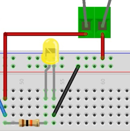
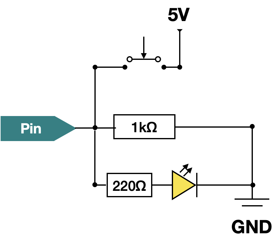
This is the circuit FYI. I include it for context, I really do not thing it is a wiring issue, maybe aside from the power source that might trouble the SD Card. The PCB board is powering the Arduino with a DC Jack and a 9V Power Supply. Everything else is powered via the 5V Arduino Nano pin. This might be a suble difference with the prototype, in which the power supply was feeding this little power module that output 5V or 3V3 depending on the jumper wire setup. On the prototype everything was running of the rails with 5V... should not matter no?

Important part of the code (for simplicity)

  // initialize the SD Card
  pinMode(10, OUTPUT);          // output, even if you don't use it
  while (!SD.begin(10)) {
    Serial.println("initialization failed!");
    ... blink to inform the user...
    while (1);
  }
  
  Serial.println("initialization done.");

and here is the write function

 // if available, open, write cLine to the file and close
 myFile = SD.open("doorlog.csv", FILE_WRITE); 
 if (myFile) {
   myFile.println(sLine);
   myFile.close(); 
   Serial.println("log is written");
   return true;
 } else {
   // error trying to open the file
   // could write to a different log file
   Serial.println("log is not written");
   .. blink the led this is where I get the error hours in...
   return false;
 }

I will check the connections on the PCB tomorrow morning. I plan to let it run during the night. I only check every 10sec, so I am not doing any type of fast writing on the card. I also .close() the filestream after each write to avoid losing any data if is power is cut.

I do not have enough experience with Arduino and feel I need to get outside help. I am building this for a friend and would like to give him something that works :grinning:

If anybody thinks the whole code would be usefull, here is the full version

#include <Wire.h>
#include <DS3231.h>
#include <SPI.h>
#include <SD.h>


DS3231 clock;
RTCDateTime dt;

bool bDEBUGMODE = false; // FALSE when in production

bool bFirstAwake = true; // to log when powering up
int iCurrentState = 0;  // 0 close, 1 open
int iLastState = 0;     // 0 close, 1 open
const int sensor = 7; // door pin


File myFile;
const int chipSelect = 10;

const int redLED = 8;

void setup()
{
  Serial.begin(9600);

  Serial.println("Initialize the LEDs");
  pinMode(redLED,OUTPUT);

  Serial.println("Initialize the sensor");
  pinMode(sensor,INPUT);

  Serial.println("Initialize RTC module");
  // Initialize DS3231
  if (!clock.begin()) {
    blinkled(redLED,2,1, true);
    while (1);
  }
  // Send sketch compiling time to Arduino
  //clock.setDateTime(__DATE__, __TIME__);   
  /*
  Tips:This command will be executed every time when Arduino restarts. 
       Comment this line out to store the memory of DS3231 module
  */

  // initialize the SD Card
  pinMode(10, OUTPUT);          // output, even if you don't use it
  pinMode(chipSelect, OUTPUT);  // The chipSelect pin you use should also be set to output

  Serial.println("Initializing SD card...");

  while (!SD.begin(chipSelect)) {
    Serial.println("initialization failed!");
    blinkled(redLED,3,1,false);
    //blinkled(redLED,3,1, true);
    //while (1);
  }
  
  Serial.println("initialization done.");
  blinkled(redLED,1,5, false);
}


void blinkled(int pin,int times, int wait, bool nonStop){
  int i = 0; // blink pin

  digitalWrite(pin,LOW); // make sure it is off
  do {
    for (i=0;i<times;i++){
      digitalWrite(pin,HIGH); // turn on
      delay(wait*800);       // wait 
      digitalWrite(pin,LOW);  // turn off
      delay(wait*800);       // wait 
    }
    delay(3000);
  } while (nonStop);
}


boolean writeStandardLog(int iState) {
  int MSG_BUFFER_SIZE = 50;
  char msg[MSG_BUFFER_SIZE];
  String sLine;

  // construction datetime string
  dt = clock.getDateTime();
  char sDatetimeLog = "";

  sLine = String(dt.year) + "/" + String(dt.month) + "/" + String(dt.day) + "," + String(dt.hour) + ":" + String(dt.minute) + ":" + String(dt.second);

 // append door state
 if (iState == 0){
  sLine += ",close";
 } else {
  sLine += ",open";
 }

 Serial.print("Preparing to write ");
 Serial.println(sLine);
  
 // if available, open, write cLine to the file and close
 myFile = SD.open("doorlog.csv", FILE_WRITE); 
 if (myFile) {
   myFile.println(sLine);
   myFile.close(); 
   Serial.println("log is written");
   return true;
 } else {
   // error trying to open the file
   // could write to a different log file
   Serial.println("log is not written");
   blinkled(redLED,3,1, true);
   return false;
 }

}


void loop() {
  int val;
  val = digitalRead(sensor); // read the current state of the door
  
  Serial.print("sensor says ");
  Serial.println(val);
  if (val == HIGH) {
    Serial.println("door is closed");
    iCurrentState = 0; // door is closed
  } else {
    Serial.println("door is open");
    iCurrentState = 1; // door is open
  }

  if (bFirstAwake || (iLastState!=iCurrentState)) { // first time powering up or state change
    Serial.println("Door movement or first rise detected, writing to card");
    writeStandardLog(iCurrentState);
    bFirstAwake = false; // don't write until reboot
  }

  iLastState = iCurrentState; // set the new current state

  // wait 10sec before another measurement
  delay(10000);

}

All your current is now going through the Nano and this is the nano generating the 5V out of the 9V input you have. So the nano's regulator (LDO) has to throw away the excess power.

Say your circuit needs 500mA, then the regulator needs to dissipate 0.5A x (9V - 5V) = 2Watts (I'm simplifying there is a diode to take into account)

There is a limit to what the onboard LDO can do, if it heats up too much then you are in trouble...

have you measured the current need of your setup? (from what I see it's not a lot, make sure there is no short)

--

consider not using the String classe esp. if you are short in memory, for example the writeStandardLog() function could be written without the need for the String class as such

boolean writeStandardLog(int iState) {
  // if available, open, write cLine to the file and close
  myFile = SD.open("doorlog.csv", FILE_WRITE);
  if (myFile) {
    dt = clock.getDateTime();
    myFile.print(dt.year);    myFile.write('/');
    myFile.print(dt.month);   myFile.write('/');
    myFile.print(dt.day);     myFile.write(',');
    myFile.print(dt.hour);    myFile.write(':');
    myFile.print(dt.minute);  myFile.write(':');
    myFile.print(dt.second);
    myFile.println((iState == 0) ? F(",closed") : F(",open"));
    myFile.close(); // edit was flush() but really need to close
    Serial.println("log is written");
    return true;
  }

  // error trying to open the file
  Serial.println("log is not written");
  blinkled(redLED, 3, 1, true);
  return false;
}

I tend to use the SDFat library instead of SD, I find it better.

Hi J-M-L

Thank you so much for your time. To be honest I did not calculate the amp requirements as it seems to be on the trivial side. An SD Card and a DHT module. If a Nano cannot support even that I would be very surprised. Maybe I am being naive. I see the SD taking 200mA and the RTC 0.2mA, so dissipation 0.22 X (9V - 5V) = 0.88Watt. Even with the LEDs and the board, I do not think overheating is an issue. Plus the board will be in a closed trailer, sitting outside in winter heated to around 60F...

This morning I saw my LED that lights when the reed switch shorts was lit :face_with_raised_eyebrow:. However, the reed switch was not triggered! First time I saw that. I spent 1hr chasing a short. Low and behold, there was a tiny speck between two solder points. I cleaned it up. It's now up and running and I will monitor its status.

I will make the adjustement to the code to avoid the String class.

Is there any reason you use flush() ? I would think that marking the file as closed with close() is cleaner as the board is expected to be shut down unexpectedly.

Thanks!

agreed - that's why I said

your reed switch has a pullup or pulldown?

yes, close() ensures that flush() happens indeed, that's actually what I meant to write. (I forgot the close)

No worries, I will add the close()

If you look at the diagram, the reed switch is fed via + on one side, then I use a 10k ohm towards the yellow LED. Also, before the 10k I connect to a digital IO set as INPUT. My (newbie) reasonning is that this pulldown resistance is between the pin and ground, and sufficient to avoid a floating state (see diagram on the right). no? I am by no means an expert in this.

2023-11-20 09_32_35-pullup vs pulldown resistor - Google Search

I don't see that here

it looks more like

or if you inverse the Red (usually 5V) and Black (usually GND) rails of the breadboard

I'm no expert either but not sure the LED would not interfere with the grounding

LEDs act as photodiodes, and generate voltages when exposed to light.

The photocurrent flow is in the opposite direction of the diode arrow, so a digital input connected to a photodiode as shown above cannot be assumed to be grounded. Voltages of 1 to 3 V, depending on LED color, can be expected.

It seems to me the bottom diagram reflects my circuit? 5V goes to Pin and 10k, and 10k goes to LED, which goes to Ground.

The pin detects the voltage change successfully, every time. Now, I am not saying it's perfect, just that from my own observations it seems to do the job fine.

If there is a way to make this better (without me unsoldering half the PCB lol) I am all hears :grinning:

I would remove the LED from the pull-down path and add it with a 220 ohms resistor to GND on a separate path on its own.

Not sure this is your issue though

What's this 3V3 (yes, 5V) comment mean??

At first glance I see the SD Card reader uses 3v3 (it says so on the board) but as many have reported, it does not work with 3v3 power supply due to voltage loss. I supply 5V at the source and let the onboard voltage regulator step it down to 3v3, which works like a charm. I just added this note to my documentation which made its way to the screenshot :nerd_face:

Mmm if on a separate path, do you mean parrallel to the path on the PIN? I want to detect the reed switch contact AND have the led light

something like this

(but I'm a software guy so I'm sure more qualified hardware members will chime in)

Does the SD board have level translators and the required pullup resistors?

If it still errors out after a few hours with all the string operations removed, you might just touch the Nano's LDO with the tip of your little finger to see if it's hot. If it is, then the next test might be to put a small fan on the Nano to see if that makes any difference.

I see. It avoids the PIN being in a floating state? The added benefit is that if my LED ever burns out, there is backup circuitry :grin:

I did not add anything else than what I found on numerous tutorials, and I did not see the usage of added resistors in them. This is the board. As previously stated I provide it with 5V and not 3v3 (which did not work, as many have found)

2023-11-22 09_01_18-Carte de stockage Micro SD TF pour Ardu37, bouclier de mémoire, technologie éven

Great idea for future troubleshooting. I have looked this morning and it is cool to the touch

Thanks all for the kind help. I think the issue was two solder points being very close together and creating unstable voltage. I scratch the area and the issue went away. It's been running 24hrs+ without issue.

I will take note of the added circuitry as proposed by J-M-L for future version as I do not want to mess with something that works without that addon...

Wow, this community is super I have to say!
:star_struck:

Which one, there is two different ones shown ?